airking: Air-King 4608A
airking: Air-King 4608A

Fellow Radiophiles,
I bought this very cute Air-King 4608a Plaskon cased radio from Radio Age editor Ed Lyon at Radio Activity, which is the annual meeting of the Mid Atlantic Antique Radio Club.
This unrestored AA5 set is not valuable and needed a fair amount of clean up and speaker repair.
Electrical repair
I added a 0.25A slow blow fuse for safety, and replaced leaky capacitors with very small modern equivalents, while leaving the original caps in place with a shunt gray wire.
The electrolytics were bad too, and were not original. I kept the electrolytic cap red green and black wires, and insulated the new pair of 50uF 160V electrolytics with red heat shring plastic. This makes the new caps look somewhat like the originals.

This set uses an anusual method of grid bias for the 50L6 output tube. The 50L6 cathode is grounded, and it's grid is tied with a 150k resistor to the local oscillator control grid, which is pin 5 of the 12SA7 pentagrid converter. This method of bias has the advantage of eliminating the need for an electrolytic bypass cap at the 50L6 cathode to bypass the usual 180Ω kathode bias resistor. Leaving this resistor unbypassed, as is often done, cuts the gain of the 50L6 stage in about half, while reducing it's distortion somewhat. Grounding the cathode in this set makes it possible to get full gain from the 50L6.
I measured the grid bias level at the 50L6 as -4.5V, and the screen B+ voltage was 68V. Both of these voltages were a bit low. Some of the weakness was due to the 2.2k screen B+ resistor having drifted up to 2.6k. I decided to bring the screen B+ voltage to a more common value of 89V by paralleling a 2k resistor with the original 2.2k. The increased Screen B+ resulted in a more robust Local Oscillator operation, which generated -6V of grid bias for the 50L6. The increaced Screen B+ also improved sensitivity noticeably.
This version of the radio came with a set of OCTAL tubes which is correctly accounted for in the Rider schematic. However, the Rider schematic left the LOCTAL sockets in place. The following schematic was rewired with the correctly pinned out OCTAL sockets.
 Keep in mind that the chassis of this radio is wired to the power line via the power switch, so the chassis may be hot when the radio is ON. I helped remedy this problem with a polarized plug and by adding a plastic film over the exposed portion of the chassis. The radio came with a replacement cord, that was not original.
Case cleanup
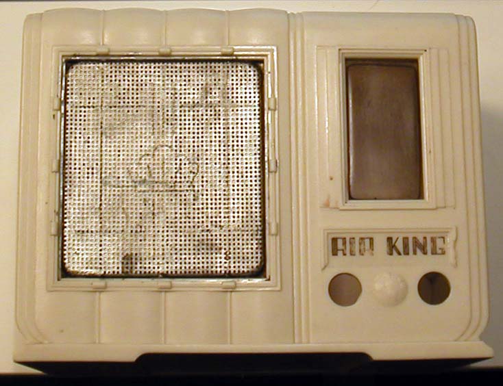 The aluminum speaker grille was originally painted with gold paint and had a decorative line pattern and a crown. Someone along the way had painted the the grille with silver paint, which left most of the grille holes clogged and further obscured a deteriorated decorative pattern. I decided to strip the grille of all paint, and perhaps, at a future date, apply the original pattern, once I find out what it looked like, exactly.
The plastic dial cover was also very dull. I made it clear again with Novus fine scratch plastic polish.
 The Plaskon case of this radio feels somewhat like Bakelite, and is impervious to every solvent I used to remove the grille and dial cover from the case. Some of these solvents included Acetone, isopropyl alcohol, lighter fluid and an aggressive label remover. The grille and dial cover had originally been glued in place with contact glue. I used this same type of elastic glue to put the grille and dial cover back.
Some signs of heat warpage are evident at the edge of the case, so I decided to protect these areas by gluing in some aluminum foil with contact glue. I also added a similar shield over the pilot light, and chose the shape of the shield to cast a nice shadow through the plastic.

The brass dial plate was finished in a dull gold, which had darkened over time. Washing this plate with Twinkle copper cleaning cream made the brass and the gold finish much brighter by gently disolving the oxidation. I am not sure if the gold finish was a kind of paint that was applied over the brass plate.

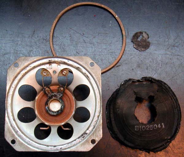
The most laborious part of the repair was the replacement of the badly warped 5 inch speaker cone. It seems that the original cone had been water damaged. After a quick search, I found no replacement 5 inch speaker cones.
 First, I loosened the contact glue at the edges of the old speaker cone with acetone, then I used an X-acto knife to cut the cone near the voice coil, while taking care not to sever the voice coil wires. I saved the edge spacer.
After 4 tries, I was able to make a cone from "construction paper" that fit the speaker very well. "construction paper" is a kind of light weight card stock used in US primary schools for paper construction projects. I found a grade that seemed to have a porous texture and weight that was similar to the orignal cone.
 The circular ridges of the "surround" were first drawn with a compass in pencil on alternate sides of the paper, then I used a ball point pen to score the pencil circles manually. Careful hand-bending of the scored circles produced the desired speaker "surround". I cut the last fold of the surround with about 16 radial cuts to let this last fold become coplanar with the speaker frame.
One of the trial cones shows a piece of removable tape that I used to train the paper into the cone shape by shaping it first into a tight cone, after the surround was formed.
There is no more than 0.1 inches of overlap at the radial cone seam.
I used contact glue to affix the surround edges to the speaker frame first. Then once this was set, I applied some contact glue over the cone-voice coil junction. This glueing sequence allowed for the original speaker spider to keep the voice coil aligned.
I glued a piece of soft felt as dust cover over the voice coil.

 I measured the frequency at which the speaker gave it's greatest output with the old cone as 120Hz. This is the self resonant frequency, and I used a simple sinewave generator for this test. The new cone resonates at 140Hz, suggesting that my cone is slightly stiffer or lighter than the original.
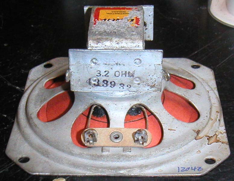
This view of the speaker shows one scored ridge I drew on the back of the speaker to break up the speaker into areas of vibration, with the inner area for the higher tones. This probably did very little.
The sound quality is very good, even at loud levels, despite the slight physical imperfections of the cone.

A while back I managed a partial replacement of a similar speaker cone in a Teletone 990 AM radio.
Hopefully, this radio will never be so valuable or so rare, that a future owner will replace the speaker with a new one. Perhaps he/she will enjoy the new speaker cone in this radio as part of radio collecting history.
Regards,
-Joe
To thank the Author because you find the post helpful or well done.
Cone Measurements
Fellow Radiophiles,
I must admit that I hit uppon the correct cone size by trial-and-error, simply by making the paper disk I cut to be somewhat larger than the diameter of the speaker.
This is clearly the hard way to arrive at a good size. I suppose the trials were not completely wasted, as they allowed me to practive folding the surround ridges.
If you plan to do a similar speaker replacement, but would like to get your final cone in fewer tries, I suggest you make three simple measurements, put these three measurements on paper and draw the profile for your new cone over the frame work of these three dimensions.
The three black lines in the diagram represent:
1-Diameter of the old paper cone at the edges, as it sits in the speaker frame,
2-The depth of the speaker to the top of the voice coil paper cylinder where the paper cone attaches,
3-The outside diameter of the voice coil cylinder.

Now you are ready to draw the profile for your new cone, using the black lines as a framework. The blue line labeled cone is what you might draw. It includes a short flat lip to glue to the frame at the outer edge, two surround ridges, and a linear extenstion of the cone profile beyond the voice coil attachment point to the center point of the speaker.
The final required radius for the paper disk is the linear sum of all the segments that you just drew. The red arrows point out the where all the various segments meet on the disk, and also mark where you will draw the various circles to score the paper and to cut the hole for the voice coil. Be sure to cut the voice coil hole only after you drew the last circle.
It may also be helpful to draw several more evenly space concentric circles in the upper half of the new cone for scoring without bending. These concentric score marks help prevent cone resonances, and tend to free up the central portion of the cone to vibrate more freely at high frequencies. This is only a minor refinement, and I can't attest to it's utility beyond trying to immitate the original cone design.
Best Regards,
-Joe
To thank the Author because you find the post helpful or well done.
Grille Pattern
Fellow radiophiles,
Ed Lyon's wife Millie, found a picture on the internet that showed the grille pattern on the Air-King speaker grille. Thank you Millie!
 The web site with the original photo of the radio can be found by searching for "John Kendall's vintage electronics". The image is associated with the sale of the radio, so it may not be there very long.
I took the photo of the radio that Millie found, and toned, sized and cropped it into this BW pattern. I printed it on transparent acetate with a 3.08" width, in a repeated pattern to serve as several masters to cut one or more stencils made from tape.
The background is painted the same gold as the dial and the pattern is in chocolate brown paint.
The clean aluminum grille shown in the next photo, was prepared for painting by roughing up the surface with vigorous shaking the grille inside a plastic box with fish-tank gravel for several minutes. After cleaning of the gravel dust, the resulting surface was dull for good primer adhesion, yet had no scratches.


After the aluminum surface was dulled by the gravel and cleaned, I applied a coat of spray primer for metal shown with the gray cap. After the primer was dry I applied several fine coats of spray gold enamel until the paint coverage was solid and opaque.


 My friend Erik Otto suggested using painter's tape to cut the stencil. I found this grade of tape that had a smooth surface and gentle adhesion that still sealed wet paint very well. This tape is also surprisingly strong and withstood repeated removal and application without tearing.
The blue tape was applied over a laser printout of the pattern on acetate, and cut with an X-acto knife to follow the pattern outlines. The blue tape is translucent enough to see the pattern. I chose acetate only because it was not easily cut while cutting the stencil on the blue tape.
As each piece of stencil was cut it was transfered to the speaker grille with fine tweezers.. The tape was not wide enough to cover the entire grille. The grille pattern was cut over three strips of tape.


Once the pattern was completely transferred to the speaker grille, it was time to apply 3 fine coats of a very opaque brown spray paint. The opaqueness of the paint made it possible to apply very fine coats and obtain full coverage. I did all the spray painting outside with the speaker grille at the bottom of a large paper bag. This helped contain the spray while spraying from about 18 inches away.


The tape is so resilient, that it did not tear after it was rmoved from the grille. I removed the tape about a half hour after the last coat of brown spray paint was applied. At this point, the paint was dry to the touch, but not cured hard, which helped avoid any rough edges in the paint pattern. I put the extra segment on the right to test the paint.
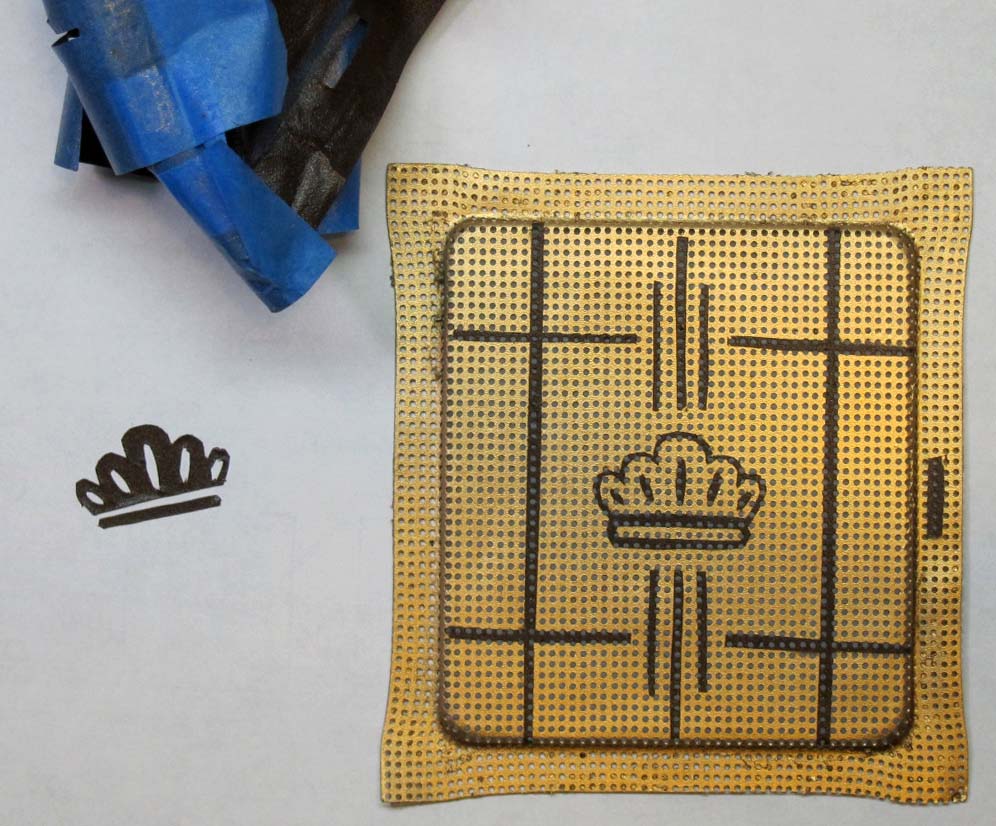
I am very pleased with the final result.

Last thougths:
The first brown paint that I tried was a thick acrylic paint that was meant to paint on canvas. This was a very bad choice because this acrylic paint did not adhere to the gold paint base when I removed the tape stencil. In fact the adhesion was so poor, that I simply scraped it off before it was completely cured. After applying one extra coat of gold spray enamel, I made the second stencil documented above.
Use a disposable plastic box to rough up the aluminum surface because gravel dust will become embedded in the plastic.
I had never done this kind of work before. I took the advice of several friends and chose a method I felt I could follow. Thank you Ed and Millie Lyon, Erik Otto, Ken Cleveland, George Barbehenn and Steve Martin.
Regards,
-Joe
To thank the Author because you find the post helpful or well done.