Dual Plate Triodes, a Review
Dual Plate Triodes, a Review

Die deutsche Fassung findet man hier.
Preface:
I have always been interested in these special tubes without a control grid. Explanations of operation are, of course, found in the old textbooks (Barkhausen, Kammerloher etc.), but they are not always easy to understand for the average radio technician like me. Sure, the target audience was different ...
This has led me to bring something down on paper in chronological order; with less theory, but more images, which were sometimes edited for clarification by me.
The first steps, USA 1906
To my knowledge, it was Lee de Forest, who was the first to achieve practical success in influencing the electron flow from the filament to the anode within a vacuum tube [1].
In the drawing below, we see two metal plates on each side of the filament. The left one is marked D’ and is the control electrode. On the other side, there is a second plate marked D, which we call anode.

The aerial V is connected to transformer T’’ and the voltage is fed to the control electrode D’. It is noteworthy that a negative bias B’’ was already inserted in the circuit at that time! Plate D (sometimes also called “wing”) is connected to the headphones (receiver R) and battery B.
Nowadays, it seems reasonable that a control electrode between filament and anode will have a far greater impact on the electron flow. It took a while until this idea –again by Lee de Forest- was put into action. See Fig.1 below. This resulted in the famous Audion Patent [2] with a control grid in the stream of electrons.
Interestingly, the former construction with the less effective flat control electrode was not yet forgotten and repeated in Fig.2. You never know…he might have thought.

Principal Function
Easy to understand seems to me the representation of the electron flow with three different bias voltages applied to the control electrode on the left.

Money rules the world….
It is well known that inventor’s rights must be respected! In other words, tubes produced commercially elsewhere with a control grid must have the permission of the patent owner. To save these costs, tube manufacturers were forced to search for means to circumvent the de Forest patent [2]. RCA had later acquired the patent rights and had agreements with other tube manufacturers worldwide, such as TELEFUNKEN in Germany.
Although it was de Forest who invented [1] the flat control electrode, it seems, electron tubes produced with such a simple control element were tolerated, because it is less effective!
Plio-DYNATRON, USA 1916
The first Dynatron by A.W. Hull consisted of a filament, a helical wire (he named it “anode”) at a high positive voltage followed by a cylinder shaped 3rd electrode at a lower positive voltage.
In order to have control over the electron flow of such a device, he later added a control grid, and the Plio-Dynatron was born. Strictly speaking, this arrangement had four electrodes in total!
Consulting the original patent documents [3], I found a variant (Fig.4) where, instead of the mentioned control grid, a so called “Discharge Control Member” was used. They had formed the filament into a spiral and inserted a metal rod (in red) in the centre of the spiral. The effect on the emitted electrons is the same as described in the beginning of this article.

PLATION, Huth, Germany 1924

Another example as tube manufacturers circumvented the control grid patent. The advertisement above shows the tube PLAV9 with four different bases.

On the left side, we see the control electrode with a notch close to the filament. The anode plate is arranged to the right. The notch is to improve the control effect and goes back to investigations by Mrs. Henny Cohn at Huth.
The small tube factory Seddig in Würzburg, Germany, built some Dual Plate Triodes too.
Magnavox A, USA 1924
The American manufacturer Magnavox produced this „Gridless Triode“ for its audio amplifiers. In the original version [4], we see the filament B in the shape of nearly an inverted V. The inner control element C was a metal sheet located in the same plane as the filament.

In the literature [5] significant difficulties with respect to reliability were reported, which resulted in multiple design changes.
Gammatron, Heintz&Kaufman, USA 1932
This producer has become associated with the term „Gridless Triode“ and is probably the best known of all.
Engineer R.M. Heintz was a successful entrepreneur in the U.S. in the field of transmitting and receiving equipment. He established his own vacuum tube factory in San Francisco. To save on licensing fees, he had to circumvent the patents on the thoriated filament, the getter and, of course, the control grid patent.
All this led to a further development of the triode dated back to 1906. I assume that the original de Forest patent [1] was no longer valid in the early ‘30s. Employee P.F. Scofield filed his patent [6] in 1932.

As an example, I would like to present the spec’s of three different Power Gammatrons They bore the names 55, 155 and 255. See table below.

These power tubes were built very robustly (Pat. [7]), as the drawing below clearly shows. Both metal plates were made of sheet tantalum. Tantalum has the capacity to bind residual gases, so no getter was required. The filament consists of pure tungsten.

Please note:
The dispute over royalty payments was resolved at a later date. After that, it was possible for Heintz & Kaufman to produce tubes with the more efficient control grid!
Over the years the name “Gammatron” became a good brand for H & K. Although the newly produced tubes no longer contained a control electrode behind the cathode, the well known name GAMMATRON was maintained!
Here some examples of tubes and a box that is NOT a Gammatron in the original sense!


This is also true for this small power tube Type 24-G

Electrometer Tube 4060, Philips, The Netherlands 1939 and later
It was shown that a Dual Plate Triode has an extremely low grid current. Therefore, if carefully designed, it can be used as an Electrometer Tube.
The Philips 4060 is such a specimen depicted here in detail. One clearly sees the two horizontally arranged plates. “Steuerplatte” = control electrode and below the “Anodenplatte” = anode. In between the “Faden” = filament which is a little bit closer (barely noticeable) to the control electrode. The latter is connected to the top cap for optimal isolation.

Epilogue
The Russian Subminiature Tubes are not in the cope of this article, and were intentionally left out. I would like to refer to the outstanding article written by Joe Sousa.
Please do not hesitate to communicate any incompleteness, errors or inaccuracies to my e-mail address, nobody is perfect…
Again, my sincere appreciation to Joe Sousa, who served as a proof-reader.
References
[1] US Patent 841 387
[2] „ „ 879 532
[3] „ „ 1 385 873
[4] „ „ 1 646 626
[5] The AWA Journal „Herbert Metcalf and the Magnavox A Tube”
[6] US Patent 1 986 450
[7] „ „ 1 930 713
To thank the Author because you find the post helpful or well done.
Gridless Tubes, just an experiment


To thank the Author because you find the post helpful or well done.
Filament voltage

Hello Wolfgang:
When I measured the 1Zh37b in Gammatron operation (see post 3) at rated filament voltage, I only got a voltage gain mu=0.35.
Your demonstration of 6X higher voltage gain of 2 for Gammatron operation of the 1Zh37B has not only brought to me a further understanding of the operation of this special tube, but also of the nature of the space charge around a cathode.
You attribute the increase in voltage gain to the reduced shielding effect of the smaller electron cloud that forms at the filamentary cathode when operated at reduced temperature.
Intrinsic voltage gain (mu) in a tube is a measure of the relative electric field influence of one electrode as compared to another electrode, over the cathode. For example, a triode with mu=10 has a control grid with ten times more electric field influence on the cathode than the anode.
The concept of "mu" was originally defined by James Clerk Maxwell to describe electric fields through metalic meshes. This concept was later found very useful in the study of grid meshes in tubes.
It stands to reason that with a mu=0.35 under full filament voltage, that the electron cloud shields much of the effect that one control rod has on the electron flow to the other rod. This proves the existence of a large shielding electron cloud that fills the space between rods g1a and g1b.
Thanks for emailing me this very nice illustration:
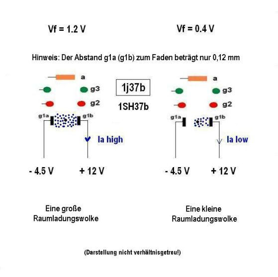
While a smaller electron cloud will conduct less current to the positive g1b rod, it also lets more of the electric field that is created by the negative control rod g1a around the electron cloud itself. The relative control of g1a and g1b over the current to g1b is now tilted in favor of g1a.
Your demonstrated gain of 2 shows that the electric field from the negative control grid rod has twice the effect of the positive electric field from the positive anode rod.
Perhaps there is a complementary effect going on at the positive g1b rod: The electron cloud that forms in the space between filamentary cathode and the positive g1b rod helps shield the cathode from the positive voltage at g1b.
The net result is increased voltage gain from 0.35V/V with full filament voltage to at least 2, as you found in your experiment. But the reduced current causes a drop in transconductance.
I have made some new curve trace measurements under reduced filament voltage to support your amplifier results. I posted then at post 10 of Russian Subminiature Tubes.
These new measurements show that the highest voltage gain is obtained before thermally limited current flow begins. Under thermally limited current flow there is little or no reserve of electron cloud for additional flow under grid or anode control.
Thank you for your very enlightening contribution.
-Joe
To thank the Author because you find the post helpful or well done.
...some additional experiments
In the meantime I have got a 6AX5 GT tube to perform more experiments.

It might be of interest to investigate the influence of the control voltage at a1 vs anode current at a2. As we already know, important for the optimal function is the right amount of emitted electrons leaving the cathode, which is Vf = 1.8V. You can’t see any glow at all!
The curves above show in the blue region a behaviour as explained in post 1 before. The negative control electrode a1 obstruct more or less the escape of electrons from the cathode’s surface. The voltage at a2 (via a load resistor) will be opposite to the steering voltage at a1. Up to zero volts, no current is drawn by a1. A further increase to + 1.5V result in maximum current to a2.
Above + 1.5V, depicted as red region, the current to the anode a2 will decrease! This means, some of the electrons are captured by the positive control electrode a1 and deducted from the anode current. You may call it “steering by electron distribution”.
As a result of this, the voltage at a2 is now in phase with the voltage at a1.
Not to old to learn…
In post 2 I pointed to a CHRS publication by John Staples and expressed my doubts about the correct measurements having regard to fig.5

With my knowledge at that time, I couldn’t explain the equal phase between Va1 and Va2. Since my new experiments with a genuine 6AX5 GT it is quite obvious, to the used (ac) control voltage a positive dc-offset bias was mixed and therefore working in the red region!
Finally
Another experiment with the popular regenerative Audion-Receiver:

In order to get maximum sensitivity, a minor positive bias of 0.7V was applied.
Believe it or not, in spite of the bad quality coils used, a firm generation was achievable…..

To thank the Author because you find the post helpful or well done.
Sodion S11...just another gridless triode
In order to make the review more complete, I would like to add the triode S11. It is an invention by H.P. Donle (USA) in 1922.

In the picture shown above we see very clearly, the Control Electrode is bended around the filament. Comparable with the „Plation“ manufactured by Huth, Germany. Below the anode (plate) is visible.
In the early 20s more of this kind of special tubes were produced. It will go too far to describe the details at this point. Please find out more here.
To thank the Author because you find the post helpful or well done.