emerson: Grid leak, Cord resistor, Reed Speaker.
emerson: Grid leak, Cord resistor, Reed Speaker.

Fellow Radiophiles,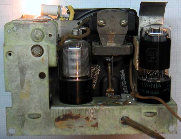
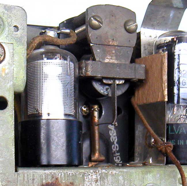
I acquired this very cute Emersonette CF255 at the most recent Radio XLI swap meet in Westford Massachusetts USA. This set is actually "collectible", which has never been a reason for me to acquire a set. What caught my eye was the high impedance reed speaker nestled between two octal tubes - a rare combination.
I replaced the dryied out electrolytics, which were not original, anyway. I used two short cylindrical surface mount 33uF 300V caps and joined them inside orange heat shring tubing.

The 0.02uF audio coupling cap C9 from the Regenerative detector plate to the output pentode grid was leaky. Instead of replacing it, I shorted it with a piece of wire and added a small 0.02uF disc ceramic in series. This helped keep the original components in the set, while eliminating the harmfull leakage. This 0.02uF ceramicdisk cap is just visible at the center of the photo.
This set no longer had the original tapped 4 terminal resistance power cord. It came with a replacement 3 terminal resistance power cord with an open resistor. I hoped to reconnect the power cord resistor. I removed the cord from the set and compared the capacitance between the two power wires with the capacitance between either power wire and the resistance wire. If the two capacitances were similar, a break in the cord resistor near either end would be expected, but I got 150pF between the power wires and only 50pF between either power wire and the open resistor terminal. The break was somewhere in the middle of the cord, so I gave up on reconnecting the cord resistor.
My alternative to repairing the tapped cord resistor shown as R7 and R8 in the schematic, was to use a capacitor to drop the line voltage from 120VAC to the 44V @ 300mA required by the heaters. This approach has the advantage of not adding any heat dissipation under the chassis. I chose two 22uF 50V Y5V chip capacitors from TDK (C5750Y5V1H226Z). I bought these at www.mouser.com and their part number is 810-C5750Y5V1H226Z.
Y5V ceramic capacitors are marketed in a special way because of their special properties. They have full rated capacitance at 0VDC, but this capacitance drops to only 20% of the rated value at the rated voltage of 50V. The voltage rating has nothing to do breakdown voltage, it simply reflects the voltage at which the capacitance is at 20% of rated value. I have tested the breakdown voltage on these caps to be about 10x higher than the rated value, around 500V.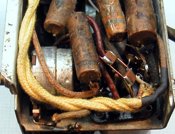 The "high-k" (high dielectric constant) barium titanate that these capacitors are made of is somewhat piezo electric, so it's best to solder them to wires instead of directly to each other or on a board, when applying voltages well beyond the rated value. Note the 1/4" gap between the two capacitors. I also added a 220k resistor in parallel to discharge the caps when the radio is unplugged.
I put the missing pilot light back in the radio, but wired it in series with the entire power path, so that the 6.3V 400mA bulb also works as a fuse. The new cloth yellow wires go to the pilot light. The original design intended that the radio still work if the pilot light goes out and the pilot light was wired in parallel with a section of the line cord resistor. I have the opposite goal in mind, for safety sake.
Distortion from loose Speaker cone
Now the radio was fully functional, but there was significant distortion in the sound.
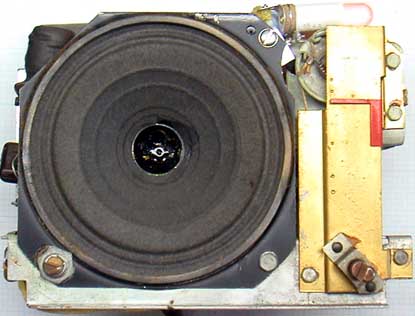
 One cause of the distortion was that the small black brass cone that attaches the speaker reed with a pin to the paper cone was somewhat loosened. I applied a some acrylic clear nail polish to the brass cone and the rattle was greatly reduced. There is still a rattle at the loudest levels, and it is not caused by the vibration of the reed hitting the speaker armature.
Update: The rattle was not completely eliminated until I reflowed the solder holding the pin to the little brass cone at the center of the speaker. This was done with a pencil soldering iron from the front of the speaker, with just a little bit of solder.
Distortion from the 0.01uF grid leak capacitor

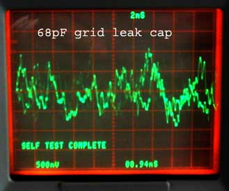
I have found over the years that if I can hear distortion, I can usually see it on the scope. Such was the case in the photo above where negative plate voltage spikes at the triode plate sounded pretty sour.
The cause of the spike distortion was the design value of C7=0.01uF for the grid leak detector. This choice can give the highest sensitivity, but at the expense of higher distortion with strong signals. The highest positive envelope peaks at the grid cause disproportionate increases in plate current. These plate current increases cause the negative voltage spikes seen in the photo above. The spikes disappear when the volume control R1 at the antenna is turned down to a level that is too soft for listening.
Turning down the volume at the antenna with R1 eliminates the distortion, but the sound becomes to soft for listening. It is also possible that the lower average modulation values used in 1939 had much fewer positive peaks than current modulation practice with sound compressors that greatly increase the number of positive peaks. I lower modulation index for the same sound level at the speaker, implies a higher carrier voltage at the grid leak which gets detected into a stronger negative self bias.
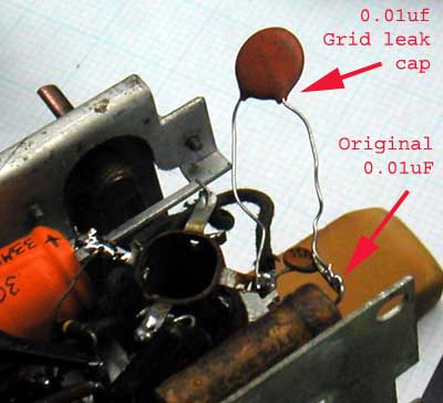
The photo on the right shows an experimental 0.01uF disc capacitor in series with the original C7=0.01uF.
There is another reason why the grid leak capacitor is used, and that is to allow for the DC bias point of the grid to be set independently by the grid leak resistor R2=10Meg. This resistor draws about 70nA from the 0.7V contact potential generated by the cathode space charge on the grid. The intention of the 70nA bias is to match the internal grid resistance to the impedance of the tuned RF LC circuit at resonance for best detection efficiency. The internal grid resistance should be between 100k and 1Meg with the 70nA DC bias.
The contact potential seen at the grid is also a function of plate voltage. Some detectors can take advantage of this by eliminating the grid-leak RC circuit entirely. The adjustment of the grid impedance is done by increasing the plate voltage until the contact potential is sufficiently lowered for a good impedance match between the LC tank circuit and the grid. For more details about grid conduction, check post #30 of Homebrew Radio.

Adding a 68pF grid-leak cap in series with C7=0.01uF lowered the grid leak time constant from 100ms to 0.68ms. The faster time constant can track the audio envelope such that the positive part of the envelope is flattened out, while pushing down the positive envelope excursions to the negative side of the envelope. For a further discussion on envelope tracking distortion check Diagonal distortion in FM limiters with special attention to post #2 by Prof. Dietmar Rudolph.
The 68pF is shown in the photo on the right connected at the coil end of the grid-leak circuit. This was convenient to experiment with, but the C7=0.01uf capacitor on the grid side of the grid-leak circuit is now floating at low frequencies, and picked up a noticeable increase in hum. The solution was to move the 68pF cap to the grid side of the grid leak circuit, so the original C7=0.01uF was grounded by the RF coil at audio frequencies. A slight re-tweak of the RF alignment was needed at the high end of the band after the 68pF cap was added.
The most comon choice for the grid leak time constant (R2*C7) is usually one that tracks the audio envelope, as became possible with C7=68pF. This gives the lowest possible distortion. One reason for the reduced distortion is that the audio content of the plate current is controlled by the negative side of the envelope, which sits at a lower distortion average negative bias.
Regards,
-Joe
To thank the Author because you find the post helpful or well done.
Hum Bucking
I was not entirely satisfied with the vestigial hum that the new C7=68pF grid leak capacitor allowed at the triode grid. The hum was coupled to the grid with stray parasitic capacitance to the heater wiring.
C7=0.01uF grid leak did not have this problem, and this ability of the 0.01uF to bypass hum was probably considered in the original design.
Nevertheless, I was not about to give up the low distortion detection with C7=68pF. The solution was to apply some hum-bucking to the audio path. This kind of trick is very common in European radios.
The grid gets it's hum as a differentiated version of the heater voltage, and this hum showed up inverted at the triode plate with 0.7Vp-p amplitude. The differentiation time constant is set by the capacitance at the grid, which is mostly the 68pF grid leak cap plus parasitics, and the internal forward bias resistance of the grid.
The non-sinusoidal shape is explained by the non-linearity of the 20uF Y5V capacitors that drive the heater string.
 After wiring 220pF in series with 560k from the offending triode heater to the triode plate, the hum was reduced to the original level of 100mVp-p at the triode plate. Bucking is made possible by the phase inversion of the plate voltage with respect to the grid, which is picking up the stray hum.
The 120us time constant of the 220pF+560k network gives a perfect cancelation of the heater hum. This means that the 120us time constant of this network is the same as the time constant at the grid. This implies that the grid impedance is somewhat less than 1.8Meg for the same time constant with C7=68pF capacitance plus parasitics.
The last trace is the Bplus voltage for the triode, which has much more hum than the plate that is tied to it via R4=500k. This attenuation is explained by an internal plate resitance near 100k.
I find that the hum is inaudible now.
The updated schematic with the hum bucking resistor:
The updated chassis layout showing the hum bucking network, along with the other new components:

Regards,
-Joe
To thank the Author because you find the post helpful or well done.
More detector bass
After listening to my repaired Emersonette CF255 for a while, I noticed that there was more bass at low volume levels, than at higher volume levels.
The reason for this is that the detector impedance at the triode grid is a function of bias current. This bias current is set by the 0.7V DC contact potential at the grid, plus the DC component of the average RF carrier, divided by the 10Meg grid leak resistor.
If the DC component detected from average carrier voltage is comparable to the contact potential, the grid leak bias current will be about twice the small signal value. The non-linear diode characteristic of the triode grid responds to this increase in bias current with an even larger reduction in average low frequency impedance, such that the new value I chose for the grid leak capacitor C7=68pF forms a low cut filter at higher volumes.
Some of this effect is desirable, as it tends to approximate the loudness sensitivity contour of the human ear. This function is usually implemented at the volume control of more eleborate radios with a capacitor, or more components, at a fixed tap.
But in this case, the low cut effect with increased signal amplitude was too strong. I moved the low cut effect to a higher signal level by increasing C7 to 168pF. Now there is good bass at normal listening levels, without the objectionable distortion produced by the original C7=0.01uF.
The increased value at C7=168pF also reduced the stray hum being picked up from the heater voltage, so I reduced the contribution from the hum-bucking network, which is now 174pF+1Meg from the 12V heater to the triode plate.
The current schematic with increased C7=168pF and reduced hum-bucking network follows:

I am starting to appreciate what all the fuss about grid leak resistors and capacitors in the 1920's was about.
Regards,
-Joe
To thank the Author because you find the post helpful or well done.