grundig: 5040W/3D Circuitry Analysis - Part 4
grundig: 5040W/3D Circuitry Analysis - Part 4

(Translation of text originally by Thomas Günzel)

Here are links to Part_1, Part_2, and Part_3 and a link to the complete_schematic_diagram.
The FM IF Amplifier (continued)
Dear friends of the forum,
To keep the threads from getting too long, we'll begin Part 4 here.
Here is another excerpt from the schematic diagram:
For an enlarged view, simply click on the diagram below!

Question 3:
On the control grid of the EBF80 there is an R-C circuit (R17/C85) similar to the one discussed previously (R24/C86) on the grid of the EF89 II.
Does this also play a role in gain regulation?
Question 4:
The suppressor grid of the EBF80 is not connected to ground; instead it is connected to the junction of C97, C98, and R41.
What is the purpose of this connection?
Enjoy!
Thomas G.
To thank the Author because you find the post helpful or well done.
AGC voltage generation
(Translation of text originally by Karl-Heinz Bradtmöller)

Hello,
Since no one else has tried to answer yet, I'd like to give it a try.
Question 3: Yes, this is another example of gain regulation (AGC).
Question 4:
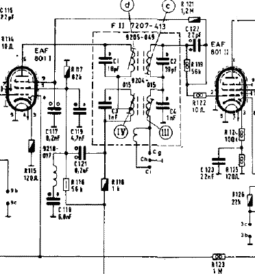
This strongly resembles the method of generating grid bias in the Grundig Ehrenfels IF amplifier, which generates the grid bias of the next IF tube EAF801 using the suppressor grid and a 1.2 Mohm resistor, and thereby regulates gain. In this case, the diode sections of the EAF801 tubes are put to work for IF AGC.
In the circuit under consideration, the diodes are housed in other tubes and serve multiple functions.
Best regards,
K.-H. B.
To thank the Author because you find the post helpful or well done.
(Translation of text originally by Dieter Barkawitz)

On question 3:
It also appears to me that this is an additional gain regulation circuit. This raises the question as to why there are two gain control loops in the FM IF amplifier, completely separated from one another?
On question 4:
The suppressor grid of the EBF80 is connected to the negative side of the electrolytic capacitor at the ratio detector. The voltage on this capacitor at the ratio detector is held symmetric with respect to ground by resistors R40 and R41. That means that when the tuning is centered, half of the voltage on the electrolytic capacitor is applied to the suppressor grid of the EBF80. As a result, the EBF80 is controlled by the tuning in a manner proportional to the signal strength, and thereby influences the steepness of the response or the tuned circuit in the ratio detector.
Regards, Dieter
To thank the Author because you find the post helpful or well done.
Questions answered properly?
(Translation of text originally by Hans M. Knoll)

Hello Herr Bradtmöller and Herr Barkawitz,
Question 3 was answered correctly by both of you. Question 4 was answered exactly by Herr Barkawitz, and Herr Bradtmöller compared it to a circuit which performs the function for both AM and FM.
The question which is still open, however is: What is all this for? I'll answer that soon...
Regards, Hans. M. Knoll
To thank the Author because you find the post helpful or well done.
Answers to questions 3 and 4
(Translation of text originally by Hans M. Knoll)
GRUNDIG 5040W 3D Part 4
At this point I recommend taking a look at this work by Prof. Rudolph, in which this subject is broadly covered.
FM_Demodulation_WS0506.pdf Thanks for allowing me to borrow pictures from it. H.M.K.
Answer to Question 3
Both of the answers that have been given, which answer the question in terms of "gain regulation" (AGC) deserve credit, although one can also view things differently.
It's correct that it functions as a gain regulator with a threshold above which a level can be kept nearly constant. This is known as a "limiter." Every thermostat works the same way in principle.
The circuit already discussed in Part 3, posts 9 and 19, is, from a purely functional point of view, identical to what we are now discussing. However, in the previously discussed circuit, an AGC voltage for the RF stage is also derived. What is still an open question is whether the limiting of a signal amplitude is the original design purpose for the circuit, or just a side effect? I'll come back to this question.
This figure shows that an AGC (automatic gain control) or AVC (automatic volume control) control voltage was also taken from the limiter in U.S. designs.
.png)
With respect to question 3 in Part 4 (i.e., here), this is a commonly used and necessary function. It is known as "limiting" or "AM suppression."
The limiting function relates to limiting the RF output amplitude of a stage or multiple stages. Figure 310 shows this:

In Figure 310 we see a linear amplifier stage which feeds RF into a subsequent stage through a bandpass filter. The second stage is the one we're talking about for question 3.
On the X-axis is the RF input signal in mV, and on the Y-axis is the output signal in volts.
Both tubes have the now familiar R-C circuit on G1. Without the R-C, the output signal would increase linearly with the output voltage, until the tube is overdriven, depending on the values of resistors on either the grid or anode. That's a situation that is never wanted. If a tube is overdriven on G1, grid current flows, and this can have a high value (mA). This diode action, however, changes the transfer function of the bandpass filter and negatively impacts the overall performance of the radio, unless this situation is controlled.
The grid current in an amplifier or oscillator can be limited by an R-C circuit, whereby the DC voltage, which follows the RF amplitude, shifts the operating point of the tube toward a more negative grid bias (Ug1) and lower anode current. This all happens smoothly, so that the action can be viewed as gain regulation.
In order to optimize the desired AM suppression, the screen grid (Ug2) must be held at the right voltage, so that the limiting of the anode current (Ia) begins as early as possible. In Figure 310, there is a relatively large resistance Rv on G2. With this large resistance, at low RF input, the point of overdriving occurs early, since the large screen grid current (Ig2) drops the screen grid voltage to a low value. That makes the linear part of the characteristic curve of Ia vs. -Ug1 short.
If the RF amplitude rises at the input of the stage, a negative voltage is developed in the R-C circuit, which reduces the anode current and the screen grid current. That causes the screen grid voltage Ug2 to climb and increases the length of the linear region. The whole effect is steady and smooth; that's why the caption of the figure mentions a smoothly tracking screen grid voltage.
In Figure 313b, I will show that the correct length of the linear region of the Ia/-Ug1 curve is achieved for all RF voltages.
This figure shows an input signal with varying amplitude (shown vertically). The anode current of the stage is shown horizontally. One can see that if the linear region is too long, or the input signal too small, the undesired amplitude modulation is either not suppressed at all, or is only limited on its positive peaks at the upper kink of the curve. The same thing happens at the lower kink. Therefore is it necessary to choose the component values carefully, in order to have effective AM suppression. Good AM suppression is really the main advantage of FM -- it allows interference-free reception.
In high performance receivers, limiter circuits like these are used in cascade.
Here is a text on this subject by one of our members:
Text 401 by Prof. Dr. Eng. Dietmar Rudolph (Copy: Hans M. Knoll)
Limiter Circuit Using Tubes
In tube circuitry, it is often sufficient to have a single limiter stage. To accomplish this, tubes are operated in a manner so that they go into saturation especially quickly, if the operating voltages are kept low. An R-C circuit is also typically used in the grid circuit. The characteristic curve shows the situation, as in Figure 5.
With a single tube, one can only achieve incomplete and one-sided limiting function. An improvement is to implement two limiter stages in cascade, as shown in Figure 6. In such a circuit, the limiting threshold is lower and the limiting function is more symmetric.
I would add that in the case where one-sided (either upper or lower) limiting is insufficient, the signal from the first stage is inverted 180° and in the second stage gets limited on the side which was previously poorly limited, and thereby any AM is eliminated.
Here is a figure from H. Prof. Rudolph:
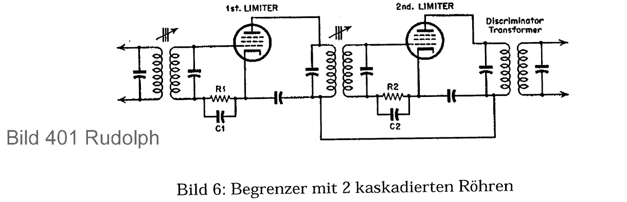
(caption above is "Figure 6: Limiter with 2 tubes in cascade")
And here is another from Prog. Rudolph:

(caption above is "Figure 5: Characteristic curve of a limiter with one tube")
In the 5040W/3D the two tubes are the EF89 II and the EBF80. This also answers why this "AGC" is used two times in series in the amplifier chain of models 4040 thorugh 5050.
GRUNDIG 5040W 3D Part 4
Remark:
Herr Günzel normally decides independently what questions he asks. In this case, I asked him to combine what we are now discussing as question 4 with his question 3. The two questions are closely related, although there was no way for him to know that. In other cases, I am not involved in the posing of questions. HMK
Answer to question 4
It was asked why the suppressor grid of the EBF80 is not grounded, but is instead connected to the junction of C96, C98, and R41?
In the discussion of question 3 it was mentioned that the design of the limiter stage must be done very precisely, since the rejection of interference on the FM demodulation due to AM interference cannot function optimally over the entire range of antenna signal strengths.
A relevant consideration is the anode and screen grid voltages on the stage before the demodulator (ratio detector), in this case, the EBF80. In the caption of Figure 312 there is a clue: note the the low anode and screen grid voltages. With Figure 310 there is another clue -- the smoothly varying screen grid voltage.
This design of the limiter stage influences the function as shown in Figure 313b and in Rudolph Figure 401. The ideal case for FM would be a low anode and screen grid voltage as shown in Figure 310.
There are in fact some radios in which both voltages, or just the screen grid voltage are provided with extremely low voltages.
NEW INFORMATION: For example, in the model CELERINA 6100 ID 11 782, which you can find here in RMorg. There you will find the AM and FM sections completely separated; in that case, there is freedom of design. This was also the case for the GRUNDIG RT50 in 1964.
What prevents the designer from doing that? For one thing, with this type of design there is little audio signal at the demodulator, and for another, there is little voltage to control the tuning eye.
In the middle of the 1950s, there were designs for which it was necessary to switch between 16 and 20 volts.
It is no problem to make a ratio detector that outputs maximum 25 volts (in order to have some headroom). However, this also produces only about 2 volts of audio signal with maximum drive (40 kHz). At that time, a moderate range of 12 to 15 kHz was the rule. However, that produces only about 0.7 V audio signal, which is too little for a normal radio design.
In addition, the AM IF is a problem. If the EBF80 provides too little signal to the diodes, then also for AM the audio signal is 30% too low, and the AGC voltage for the RF stage and the tuning eye is too low. Everyone knows that if the tuning eye indication is too weak, it is likely to be particularly bad for AM.
Therefore, one cannot operate the EBF80 with too little voltage.
At that time, there were many radios that switched the screen grid voltage of the last IF stage between AM and FM. SABA, Siemens, etc. That however requires a switch in the FM section, where there usually isn't enough room. Otherwise the switch wiring could carry 10.7 MHz from the rear where the signals are large to the front (ECH) where small signal levels occur. That causes feedback which does not lend itself to a good design. In 1953 (as far as I can tell) Philips came out with a switching method that didn't require a switch.
Figure 403

This text comes from this Philips article. It can't be said better!
Suppressor grid control of the tube before the ratio detector: To improve the limiting of the ratio detector for FM reception, it is desirable to regulate the gain (AGC) of one or more stages and to allow the last IF stage to function as a limiter. For the case of normal AGC on the control grid, the AGC voltage for both AM and FM have to use the same wiring. If different tubes should be regulated for AM and FM, a switch must be used in the AGC circuit. For the new Philetta BD223 U-K, the AGC lines are separated, so that for FM the IF stage UF85, the AGC is applied to the suppressor grid. This tube otherwise functions as a prelimiter on its grid. This circuit is shown in Figure 403.
From here the text is mine (Hans Knoll). Since the ratio detector, by virtue of the double pre-limiting on G1 and G3, receives a nearly constant IF signal amplitude, it can be designed for a small amplitude range. This has a great advantage. If a low screen grid voltage is used, then the tuning eye control voltage (the DC voltage at the ratio detector) is small for small signal levels.
If the gain is regulated before G3 of the driver stage, it happens only at fairly high DC voltages on the ratio detector, and therefore on G3 of the EBF80. Therefore, for small signal strengths, there is little or no AGC and therefore no reduction in the control voltage for the tuning eye, which is what is desired. As an alternative, it is possible (and also done in practice) to use voltage dividers to apply optimal voltages to G3 and the tuning eye, so that the ratio detector can have the highest voltage, and the other points can have the appropriate voltage. There are examples of this.
Figure 405

This is now a very clever design which is multifaceted.
Just an example: If the limiter stage is designed so that its output voltage saturates very early, the ratio detector voltage can no longer be used for tuning, since it doesn't change any further. As everyone knows, later FM tuners therefore had a centering meter.
In sets with good FM design, the DC voltage from the limiter stage or an RC circuit in the limiter stage was used for tuning, since these voltages are tied to the signal strength over a wide range of antenna signals. If one finds R40 (20M) in the circuitry of the 5040W 3D, it will be seen that it serves as such a link: Ratio detector voltage / limiter. There the limiter level of the EBF80 is taken as a voltage at R17 and C58 and added to the ratio detector voltage, since the ratio detector voltage stays constant at high RF signal levels, and therefore would not be useful for tuning to maximum signal strength.
All of the measures discussed above, even though they appear to be simple, together make a good design.
The GRUNDIG 5040W 3D exploits all of these techniques except the reduced screen grid voltage on the tube before the ratio detector (EBF80). An important feature is the symmetric ratio detector. Already in 1947 the inventors of the ratio detector pointed out that a symmetric ratio detector is better and provides equal AM suppression over its bandwidth. The original ratio detector is a symmetric design. See here Figure 404, the original from S. W. Weeley and J. Avis from RCA in 1947.
Figure 404

With the introduction of the EABC80, the asymmetric ratio detector became the standard, because of the limited pincount of the tube.
With that, I consider questions 3 and 4 answered from my side.
Enjoy, Hans M. Knoll
Attachments:
- Limiter Nowak (28 kb)
- Limiter Function Riders USA (45 kb)
To thank the Author because you find the post helpful or well done.
Questions 3 and 4 have been completed
(Translation of text originally by Hans M. Knoll)
To show how the DC level at the ratio detector and the audio voltage level respond to changes in the RF input voltage in a standard radio design, I have included some measurement curves of the type we often made in the laboratory.
The red curve is the DC level at the ratio detector and the black curve is the audio voltage at the ratio detector, and you can see that they run exactly in parallel. The green curve is the G1 voltage on the R-C circuit of the stage before the ratio detector. There you can see that at the point where the ratio detector no longer shows any change, the limiter is already at 50%.
This radio also has the AGC applied to G3 of the tube before the ratio detector and also on the preceeding IF tube. That means the AGC applied two times on G3.
Hans M. Knoll
Attachments:
- Grundig TS 58 AGC/Limiter Curves FM (161 kb)
To thank the Author because you find the post helpful or well done.
A big 'thank you'
(Translation of text originally by Thomas Günzel)
Dear friends of the forum,
At this point I'd like to give my sincere thanks for the detailed and understandable answers from Hans on this not entirely trivial subject. Personally, as a "youngster" when it comes to tube circuitry, I have learned a great deal!
The next step along the way would have been the ratio detector with the EAA91. However, the function and circuitry methods for this have already been described in detail by Professor Dietmar Rudolph here:
As a result, further explanation by Hans is not necessary.
Therefore we will soon launch into the AM section and go through it from the antenna input up to the detector.
An appeal to all those who have questions, but don't have access to post in this thread: Simply send questions to me by email, and I will add them to the list of questions in your name.
I hope everyone enjoys the next series and hopefully we will have many questions.
Thomas Günzel
To thank the Author because you find the post helpful or well done.
(Translation of text originally by Andreas Steinmetz)

I would also like to express my thanks to all contributors. Naturally Herr Knoll is at the top of the list for his really valuable contributions, which have made me say "Aha!" again and again. But I'd like to thank everyone else, too, including those who have worked in the background. Due to lack of time, I couldn't participate this time.
However, before we go further with the FM demodulator, I would like to address an important detail: Who would like to post something about the peculiar circuitry used to decouple the screen grid and anode circuits in both IF stages? I'm thinking about the circuitry of C79/80 and C85/59.
We'll wait for answers. If no one responds, I would be happy to take this one on.
Andreas
To thank the Author because you find the post helpful or well done.
Minimizing thermal noise
(Translation of text originally by Karl-Heinz Bradtmöller)
Hello Herr Steinmetz,
I'll give it a try:
Resistors are not ideal components -- if current flows through them, the molecules making up the resistor are set into thermal excitations.
In order to minimize the resulting thermal noise and keep it out of the signal as much as possible, capacitor C59 is put in parall with resistor R14, and capacitor C80 is in parallel with resistor R21.
Best regards,
K.-H. B.
To thank the Author because you find the post helpful or well done.
Schematic diagram excerpt for question 5
(Translation of text originally by Thomas Günzel)
Dear friends of the forum,
For better understanding, here is an excerpt from the schematic diagram.
Thomas G.

To thank the Author because you find the post helpful or well done.
On question 5
(Translation of text originally by Andreas Steinmetz)
Hello Herr Bradtmöller,
In the context of IF stages, specifically the screen grid and anode circuits, thermal noise voltages don't play a relevant role. As you have correctly stated, the capacitors under discussion, together with the resistors leading up to them, form low pass filters to decouple RF from the power supply. In other words, the capacitors "block" RF from traveling beyond the circuitry of the stage they are connected to. So far, so good.
But that is not all. You correctly observed that two capacitors are connected in series. However, your conclusion doesn't capture everything: In addition to their primary function as low pass filters, there is an additional function, which is evident from the fact that the anode decoupling capacitors C80 and C59 are not connected directly to ground, but are instead connected to the screen grid bypass capacitors C79 and C85.
Perhaps you'll see the underlying reason for this, if you consider the fact that for RF, there is still a (fairly) small voltage on the capacitors. How is this voltage divided among the two capacitors, and with what phase relationship?
Andreas
To thank the Author because you find the post helpful or well done.
(Translation of text originally by Andreas Steinmetz)
Dear colleagues,
Too much radio silence isn't good, so I will shed a little light on this subject. Later I'll post an exact explanation and then I'll add a link to it here.
Here are the most important points in brief: Keeping in mind on one hand the parasitic capacitance present on the anode due to the tube itself and the surrounding circuitry, and on the other hand the two decoupling capacitors, one can recognize that there is a capacitive voltage divider (three point type) which divides the AC signal voltage in the output circuit. Therefore an RF voltage appears on the screen grid with phase opposite that of the anode signal. This voltage is indeed very small, but it is sufficient to neutralize the harmful effects of interelectrode capacitance (which results in some feedback) between the control grid and anode. Therefore this is another case of a neutralization bridge. Without this, the transfer curve of the IF amplifier would be asymmetric, which could perhaps be compensated by adjusting the alignment with a wobbler. However, the circuit would unfortunately become in principle unstable. In a top-notch design one is therefore inclined to neutralize the feedback capacitance and eliminate the root cause of the problem. In principle, one could also feed the neutralization signal directly into the control grid circuit, but one can save the cost of additional components this way and get the same effect.
When repairing these radios, one must be careful not to appreciably bend the wiring, since this can affect the stray capacitance. In addition, the choice of decoupling capacitors is critical, since at 10.7 MHz, slight variations in the lead lengths can have a considerable effect on the neutralization bridge. Obviously, the grounding point should also not be changed.
Andreas
Edit 4/7/07: The article is now finished: Neutralization in the IF Section of FM Receivers
To thank the Author because you find the post helpful or well done.
Question 5 has been answered
(Translation of text originally by Hans M. Knoll)
Hello Forum, hello Thomas G. and Herr Steinmetz,
Question 5 has been aswered correctly by Herr Steinmetz. We'll wait to see what he adds in the text he is preparing. After that, If it looks like I can add something further, I'll do that.
Greetings,
Knoll
Addendum: The only thing to add is the first class article that Herr Steinmetz posted.
One could not do a better or more detailed job!
Hans M. Knoll
To thank the Author because you find the post helpful or well done.
Question 6
(Translation of text originally by Thomas Günzel)
Dear friends of the forum,
I received the following e-mail from Herr Schlemm:
Hello Herr Günzel,
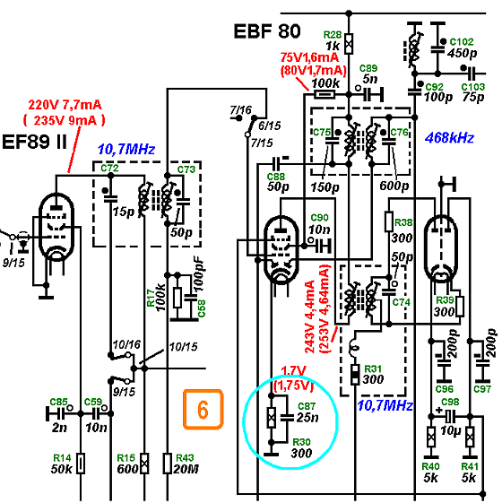
I've been following the circuitry discussion on the Grundig 5040 with great interest. Perhaps the following would be of general interest: What is the purpose of the combination of R30 and C87 on the cathode of the EBF80?
I have seen similar combinations (sometimes just the resistor without a capacitor in parallel) fairly often in dedicated FM-only IF amplifiers, without understanding what they're for.
With friendly regards,
Ernst Schlemm (GFGF*)
Who can provide a tip on this one?
Sincerely,
Thomas G.
* GFGF = Gesellschaft der Freunde der Geschichte des Funkwesens, a major anitique radio organization in Germany
To thank the Author because you find the post helpful or well done.
(Translation of text originally by Dieter Barkawitz)
Remark on question 5:
It occurs to me that the comparitive values of C97 and C80 (10 nF and 2 nF, respectively) are reversed compared to C85 and C90 (2 nF and 10 nF). Is this simply a notation error, or does the EF89 II need more neutralization than the EF89 I ?
On question 6:
The cathode resistor R30 sets the operating point of the EBF80 via negative current feedback for good DC stability. Cathode current flows through R30, and the voltage drop across the resistor raises the potential of the cathode with respect to ground. The control grid is connected to ground via R17 and as long as there is no IF signal, the grid is at 0 volts, so that the grid is negative with respect to the cathode. However, depending on the IF signal strength, grid current flows through R17, which further increases the negative bias with increasing signal level (see answer to question 3).
From the above, the following can be determined:
R30 sets the operating point, which shifts toward less amplification with increasing signal level via the action of R17.
C87 increases the feedback of R30 for AC voltages at the IF frequency, so that the full amplification of the tube can be used.
P.S.: At this point I would like to sincerely thank Herr Knoll and Herr Steinmetz for the very detailed, yet easily understandable explanations!
Regards, Dieter
To thank the Author because you find the post helpful or well done.
On question 6
(Translation of text originally by Dietmar Rudolph)

The diodes in the EBF80 provide for AM demodulation and generation of the AGC (automatic gain control) voltage for AM operation. If the cathode of the EBF80 were connected directly to ground, even for very weak signals an excessively large AGC voltage would end up being applied to both EBF89 tubes. That would result in a low AGC slope. Since the cathode of the EBF80 is at around +1.7 volts, the received signal must be at least large enough to overcome this voltage. This results in a "delayed" AGC, which leads to better AGC behavior. The EBF80 itself is not controlled by the AGC. This also increases the slope of the AGC gain regulation. Therefore it is necessary to let this stage operate in the linear regime. The RC combination on the cathode serves this purpose, setting the operating point.
For FM operation, this RC combination has no negative effect, since the IF signal already has such a large amplitude that limiting occurs with help from R17 and C58.
The schematic diagram is complicated to understand, since the order of the two EBF89 tubes is different for FM and AM. For FM, the order is I and II as shown. For AM, the EF89 II is an aperiodic precursor stage for the mixer ECC82 (1st triode).
Best regards, DR
To thank the Author because you find the post helpful or well done.
Question 6 complete?
(Translation of text originally by Hans M. Knoll)
Hello Herr Barkawitz, hello forum,
What's that I see? A comrade-in-arms, Herr Professor Rudolph.
Question 6 has been answered perfectly, as long as one understands the tip regarding R17 and the answer to question 3 to mean that it shifts the operating point for FM only.
For AM, it does nothing. It inhibits the AGC; if it did not, the AM modulation would be lost!
Your answer is correct, I've just broadened it...
Edit: The answer from Herr Barkawitz for the first part of question 6 is correct insofar as we are discussing the FM section first, and then later the AM section.
Still unanswered is what is in parintheses: Why are there cathode resistors with no bypass capacitor, alone or in combination with another bypassed resistor? P.S.: I have already dealt with this subject in detail in RMorg, but who has read it?
On question 5:
Properly observed and understood! With the article by Herr Steinmetz, one should see it the way you do.
I saw that the moment Herr Steinmetz posted the question.
Sometimes backwards; sometimes forward -- why did they do that?
As you suggest, the Grundig company made of mess of this.
After Easter, do I want to explain how?
Edit 4/13/07
Here is an excerpt from a schematic in which both capacitors have a value of 10 nF.
.png)
Here it can be clearly seen that one value was changed from 10 nF to 2 nF by hand.
.png)
Since the 2 nF capacitor goes to ground on the second EF89, and it doesn't make much sense to change the capacitor that goes from the filter to g2; that would be changing the neutralization in the opposite direction compared to what is used in the other EF89.
Therefore one could assume, as I do, that the schematic diagram is wrong.
Hans M. Knoll
I would also be happy if someone could find a practical application for our work, which is not totally simple and was also expensive!
Hans M. Knoll
Happy Easter.
To thank the Author because you find the post helpful or well done.
(Translation of text originally by Dieter Barkawitz)
My sincere thanks to Herr Rudolph for his words of explanation, which have turned my thoughts in a completely different direction, and have thereby motivated a few new questions.
You write:
"If the cathode of the EBF80 were connected directly to ground, even for the weakest signals an AGC voltage would be generated, which would immediately reduce the gain of both EBF89s. That would result in a low gain regulation slope."
Right away I can understand the immediate application of the AGC voltage and its associated gain reduction in the two EBF89s, but why does this result in a low gain regulation slope?
"Since the cathode of the EBF80 has a potential of around +1.7 V, the received signal has to be at least as large as this voltage to overcome it. In this way, a "delayed" AGC is created, which provides better AGC behavior."
If I understand this correctly, it means that both diodes in the tube are in series with a reverse bias of 1.7 V, which makes the diodes appear to have a higher forward voltage drop. As a result, the take-off point of the AGC voltage is shifted upward by this voltage (here 1.7 V). Is this also referred to by the expression "delayed" AGC?
"For FM this RC combination has no negative effect, since the IF signal already has such a large amplitude, that some limiting is accomplished with help from R17 and C58."
Of course there would also be no negative effect if the tube were in the linear regime. In any case, I don't understand why the FM IF signal generally has such a large amplitude that R17 works as a limiter. The amplitude of the FM IF signal is directly related to the FM input signal, so wouldn't it be quite small if the input signal were very small?
- - - - - - - - - - - - - - - - - - - - - - - -
I would also like to thank Herr Knoll for his explanations! And a few remarks:
"as long as one understands the tip regarding R17 and the answer to question 3 to mean that it shifts the operating point for FM only."
Is it possible to view this in an entirely different manner? How can an AGC voltage (delayed by the voltage on R17 and the operating point of the tube) be developed, when there is no FM signal present (which is necessary to develop the AGC voltage) because the radio is set to AM?
Your question:
"Still unanswered is what is in parintheses: Why are there cathode resistors with no bypass capacitor, alone or in combination with another bypassed resistor? P.S.: I have already dealt with this subject in detail in RMorg, but who has read it?" I would have gladly read it if I had found it!
For your question I already wrote the following in post 15:
"C87 increases the feedback of R30 for AC voltages at the IF frequency, so that the full amplification of the tube can be used."
In general, one can say that a cathode resistor often performs multiple functions simultaneously:
- it sets the DC operating point
- it determines the current feedback for the signal
- it shifts the forward voltage drop of a diode (as we have seen above)
- etc.
The capacitor in parallel increases the current feedback for the signal. If one desires a small current feedback, the cathode resistor can be divided, with a capacitor bridging only part of the total resistance. In addition it is also possible to create frequency dependent versions of the cathode resistor; for example, when the effective impedance of the parallel capacitor is quite high for the signal, or when a resistor is placed in series with the bridging capacitor, etc., etc.
Happy Easter Monday to everyone,
Dieter
To thank the Author because you find the post helpful or well done.
Mistake by Knoll
(Translation of text originally be Hans M. Knoll)
Hello Herr Barkawitz,
This statement I made is wrong:
"as long as one understands the tip regarding R17 and the answer to question 3 to mean that it shifts the operating point for FM only."
Unfortunately I (Knoll) overlooked the fact that G1 of the EBF80 is switched in this radio between AM and FM, unlike almost all other radios.
You wrote:
Your question:
"Still unanswered is what is in parintheses: Why are there cathode resistors with no bypass capacitor, alone or in combination with another bypassed resistor? P.S.: I have already dealt with this subject in detail in RMorg, but who has read it?"
You wrote:
I would have gladly read it if I had found it!
My response: That simply goes to show that there is more available than what what you show (in all answers).
I'll post some additional details on that!
Greetings, Knoll
To thank the Author because you find the post helpful or well done.
On the question from Herr Barkawitz
(Translation of text originally by Dietmar Rudolph)
The RC combination on the cathode of the EBF80 is only necessary for AM oepration (468 kHz); for FM the cathode could be connected directly to ground, if limiting were the only function desired. But perhaps there is another "trick" here together with suppressor grid AGC control of the EBF80, which Herr Knoll explained.
In any case, the RC combination on the cathode is primarily necessary for AM. I've learned that discussion of the AM section is not intended at this moment. Nonetheless, I don't want to withhold the requested answer.
Here is a scan from Terman Radioengineering which shows the AVC (automatic volume control) characteristic curves:

The "output voltage" can be understood as a DC signal proportional to the carrier amplitude (which controls the Magic Eye) or as the amplitude of the demodulated signal, since both are proportional to one another.
The "characteristic without AVC" is the amplification transfer curve of the apparatus. The steeper this transfer curve is, the greater the amplification. It is linear, so that no distortion occcurs. Without AVC, the volume of the received signal would increase if the station got stronger. That's the way it worked with unsophisticated radio designs: Depending on reception conditions (fading), one either heard virtually nothing, or the receiver was overloaded.
With the "simple AVC" there is feedback by which the amplification is reduced, and this is shown in the flatter curve (b).
If one assumes a particular amplification factor as a given, then, in an ideal receiver, above a certain minimum field strength, the output signal would be constant as in curve (a).
To get close to this ideal response, the gain should not be controlled up to the point of this minimum field strength, but start beyond that point. This minimum field strength produces at the AGC demodulator (left diode of the EBF80) an associated negative control voltage. If at this point, the cathode of the demodulator diode is placed at an equally high positive potential, then the sum of these voltages is 0 V with respect to ground. If the field strength of the received signal increases further, a negative voltage is generated with respect to ground, which is used to control the gain of various tubes.
From the point of view of control theory, this is an example of feedback, but it starts to take effect at a sufficiently strong field strength, and is therefore referred to as "delayed." (For control theorists: In a "normal" control loop, the fedback signal amplitude is subtracted from the input amplitude. On the other hand, for an AVC, there is a division of the IF voltage by the control voltage and no subtraction. For this reason the AVC has greater effect, the more stages it governs.)
The more stages that are controlled, the better the AVC is (curves c and d). If the control voltage is further amplified, it has the effect of increasing the gain of the control loop, and the outcome is even better (e). This can be done except for the fact that, as in the Grundig 5040W 3D, the IF is amplified in a linear stage immediately before the demodulator. This has a positive effect on the linearity of the demodulator.
For FM operation, in principle, a similar transfer curve is desired as for AM. Since the information for FM lies in the zero crossings of the RF cycles, the same kind of transfer curve is achieved by using a limiter. At the same time, one eliminates interfering amplitude variations of the FM signal, since these would show up as interference in the demodulated signal at the output of most types of FM discriminators. The limiter amplifier in the Grundig 5040W 3D has three stages (EF89 I, EF89 II, and EBF80). The EBF80, as the third stage, receives the strongest signal, and therefore the RC combination on the cathode has no ill effect.
Greetings, DR
To thank the Author because you find the post helpful or well done.
(Translation of text originally by Dieter Barkawitz)
I have been reading the explanations by Herr Rudolph with great interest, and I'm enthused about the method and approach he uses. Unfortunately these days it's somewhat rare to find complex subjects explained in an easily understandable form.
In summary -- thanks again for your efforts to provide something we can learn from presented in nice manner.
Greetings, Dieter
To thank the Author because you find the post helpful or well done.
Completion of question 6
(Translation of text originally by Hans M. Knoll)
Hello forum,
There are two additional items related to question 6 that haven't been answered yet.
Herr Rudolph asked whether the RC combination on the cathode had any function for FM, other than that which Herr Barkawitz already discussed in post 15.
My answer is no; for FM no RC is needed, just as you see on both EF89 tubes.
There is also an unanswered question from Herr Schlemm as to what the function of a cathode resistor without a bypass capacitor is.
The function of the component is current feedback. This is done in order to reduce or eliminate the input capacitance in response to changes in -Ug1 (control grid voltage), which affect the space charge capacitance. Otherwise the circuit would be detuned by limiting or AGC action. Particularly relavent to TV and stereo equipment.
There is an article on this subject by me from 2004, which Herr Schlemm would really find informative.
Here is a link to it:
Why the EAF801 tube was created
If there are further questions, I'll be glad to answer them, even if they are not related to the 5040W 3D.
Hans M. Knoll
To thank the Author because you find the post helpful or well done.
Continuation

To thank the Author because you find the post helpful or well done.
 Thread closed by a moderator. But replies can be made through a moderator.