HOW TO ASSEMBLE THE GAMMA “SUPRADYNE” WITH SIX VALVES
HOW TO ASSEMBLE THE GAMMA “SUPRADYNE” WITH SIX VALVES

HOW TO ASSEMBLE THE GAMMA “SUPRADYNE” WITH SIX VALVES
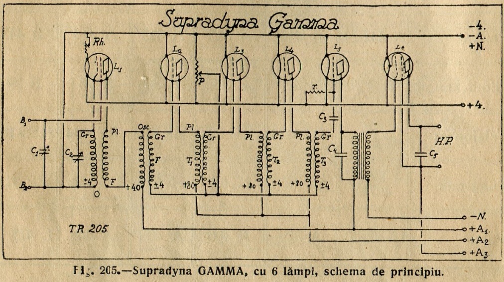
The set could be easily put together following the circuit diagram (fig. 205), which contains all the necessary details for properly assembling the kit. Anyway any further doubts should be removed after consulting also the wiring diagram:
To assemble all the components two ebonite mounting panels are used, one vertical (fig. 206) and one horizontal (fig. 207), affixed in a 90 degrees angle, the last one leaving underneath some 7 cm to the bottom to allow room for placing the components. The precise dimensions are to be found in the drawings and in the components’ list.

The connections running above the horizontal panel are represented with dotted lines and those underneath with continuous lines. On the horizontal panel above on the right the binding post B is an usual 4 mm banana socket employed to connect the pentode screen grid to the needed anodic voltage. The loop antenna is connected between the B1 and B2 binding posts and the loud speaker between the H.P. binding posts. The C4, C5 capacitors are not compulsory; if the sound stays convenient, without them, there is no need to be connected.

The symbols used in the schematic diagram for the power supply binding posts have the following meaning:
-A.: the negative pole of the anode battery.
-N, +N: the negative and the positive pole of the bias battery.
+A1, +A2, +A3: positive voltages.
The +A1 voltage for the convertor and the detector tubes should be around 50 volts, so that the first tube could oscillate normally. The +A2 voltage, for the intermediate frequency stages should be around 80 volts; a higher voltage would bring the tubes to self-oscillate; one should choose the highest voltage still assuring a quiet reception. The +A3, voltage should be between 130 - 150 volts.
Following components are used for this set:
2 slow motion 500 cm variable capacitors. (C1, C2).
1 fix capacitor 200 cm (C3).
2 fix capacitors 2000 cm each (C4, C5). Their value (not being critical) could be increased up to 5000 cm.
1 heating rheostat 10 ohms (Rh) – could have up to 30 ohms.
1 potentiometer 400 ohms (P).
1 grid leak resistor 2 Megohms (r).
1 "GAMMA" oscillator 200 - 2000 m (O).
1 "GAMMA" filter (F).
3 "GAMMA" intermediate frequency transformers 4050 (T1, T2, T3).
1 low frequency transformer 3 / 1 ratio (T4).
10 tube sockets.
1 ebonite plate 200 X 375 X 5 mm (vertical panel).
1 ebonite plate 200 X 360 X 5 mm (horizontal panel).
1 ebonite plate 240 X 70 X 5 mm (for batteries’ binding posts).
11 banana sockets 4 mm.
10 meters connecting wire.
Corners, screws, etc.
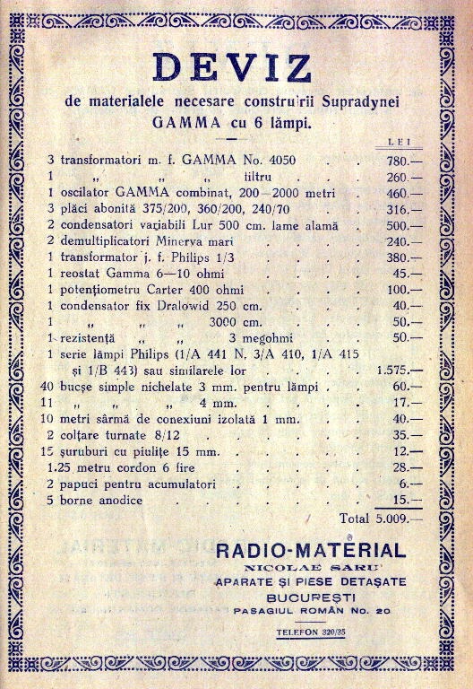
[The publicity section of the book contains at page 297 an advert from one of the main radio-parts supplier in Bucharest in those times: “RADIO-MATERIAL NICOLAE SARU” offering the complete set of components for the kit:]
For the valve list please refer to the previous set.
[Which I scanned and added bellow:]

This set represents a record. It provides a surprising performance – the best one can require from a radio set – and, as the quote shows, the price is extremely convenient. Above all, the small size of the set ensures a nice appearance.
******
Attachments:- GAMMA_SUPRADYNE6_VER (212 KB)
- GAMMA_SUPRADYNE6_HOR (236 KB)
- GAMMA_SUPRADYNE6_sch (259 KB)
- GAMMA_SUPRADYNE6_Quote (239 KB)
- GAMMA_SUPRADYNE6_Valves (73 KB)
To thank the Author because you find the post helpful or well done.