marconi: Is this a late Cockaday?
? marconi: Is this a late Cockaday?

Is this a late Cockaday?
I acquired recently (11.12.2016) the Marconiphone 221 without valves. Not being able to find anywhere a circuit diagram I had to draw it myself following the wiring on the chassis:
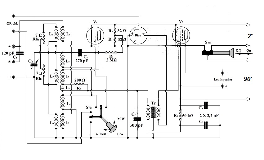
As I finished the drawing I was struck by the peculiarity of the means employed to control regeneration and antenna input level:
L7 – the regeneration coil (tickler) wound flat on the cardboard (Pesspan) tube is physically covered by L9 - only 3 turns of thick wire covered with “spaghetti” (Varnish). L7 is connected in series with L8 – only one turn of the same thick wire and also covered with “spaghetti”. L8 has the carbon resistor R5 (of about 200 Ω) connected in parallel.
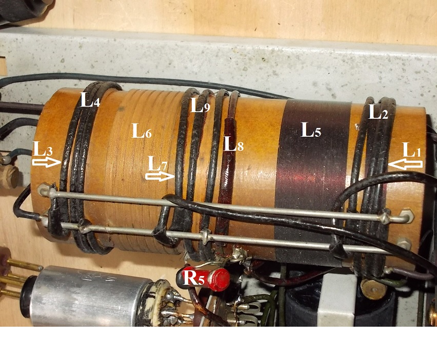
Arrows point to the fine windings on the tube, not always visible, being physically covered by the thick brown damping windings.
The rheostat Rh2 is connected in parallel with L9. By varying its value one varies the damping produced by L9 upon L7 and controls regeneration. (I am at a loss concerning the function of L8 parallel with R5.)
The rheostat Rh1 controls, the amplitude of the input signal and simultaneously the input bandwidth by varying the damping produced by L2 and L4 upon L1 and L3.
How could I name this way of controlling regeneration if not a late “Cockaday”? I know of late “Schnell” regeneration receivers where the variable capacitor parallel with the tickler was replaced by a rheostat. They are still called “Schnell”.
Best Regards,
Pitagora Schorsch
Leverkusen 14.01.2017
Attachments:- Coils (219 KB)
- Circuit Diagram 2V (85 KB)
To thank the Author because you find the post helpful or well done.
No, I don't think so...

Dear Mr. Schorsch
If you are refering to the "Cockaday Four-Circuit Tuner", his idea to reduce the positive feedback was done by close coupling of an L-C Circuitry, called "Stabilizer". The single winding was for compensation of the unwanted 2nd response (inherent to the "Stabilizer") only.
Your Marconiphone set uses L-R Circuitries for the damping action.

I made a new drawing to make things more clear.
We see a normal Grid Leak Detector switched to LW reception. Coils 7 + 8 are the tickler coils in serie . In order to control the amount of feedback, additional windings L9 are close coupled to the said tickler coils. Rh2 (= Regeneration) will more or less shunt L9.
We know, local radio stations produces often too much HF-voltage at the input of the set. To reduce the Loudness of the received signal, another damping rheostat Rh1 was wired to L2 and L4 in serie. Again, those windings are closed coupled the antenna coils L1 + L3.
MfG
To thank the Author because you find the post helpful or well done.
more...
Having thoughts about the thick wire L8 in series with L7 my estimations are:
This will help to keep the regeneration control fairly stable over the entire range. For this reason, a resistor R5 was added too.
Talking about the presumed similarities with the Cockaday Four-Circuit Tuner:
In the first place, the regeneration principle is different. Cockaday made use of the Ultraudion by US Patent 1170881 (de Forest), application filed 12-3-1914. No tickler coil needed.
With your Marconi we see a Regenerative Receiver after Eugen Reisz, US Patent 1234489, application filed 9-4-1913. The tickler coil gives feedback to the grid circuitry as it is well known to us since ever...
You mentioned the term "late Cockaday". To my knowledge, there was -except for homebrew projects- no commercial exploration of his brainchild in the later years (ten or more). In the US monthly 'Popular Radio' and other radio related magazines <other companies> advertized ready-made Cockaday-Coils in the early twenties and surely sold a lot ...
Who can prove me wrong ?
MfG
<Edited>
To thank the Author because you find the post helpful or well done.
I tend to see things different
Dear Mr Holtmann,
Thank you very much for redrawing the circuit so that everybody can understand. I must admit my drawing looks somehow complicated.
I am not exactly referring to the “Cockaday Four Circuit Tuner”: I could not possibly pretend the Marconiphone 221 I acquired, build probably around 1930, is an exact copy of the set Mr. Laurence M. Cockaday published (I think) in May 1923. But I was trying to suggest it could be a late development of Mr. Cockaday’s idea of controlling regeneration through energy absorption from the oscillating circuit, using a separate inductive coupled winding.
I suppose the designer of the Marconiphone 221 knew about Mr. Cockaday’s tuner and tried to implement the general idea with the means he had around 1930:
One can speculate that Mr. Cocaday had to choose a strong oscillator like the “Ultra” of Lee De Forest to match the particularities of the valve he was using. The designer of the Marconiphone using a “hard” valve could afford to use the Reisz regeneration. The “Ultra” not having a tickler the “stabilizer” should be coupled with the tuning circuit with the inherent detuning effect Mr. Cockaday tried to compensate. Choosing the Reisz regeneration (or any other having a tickler) the detuning effect is reduced, the “stabiliser” being coupled with the tickler.
It is known that the Cockaday “stabilizer” was tuned to damp the second harmonic of the received frequency also must have had a smaller coil or capacitor or both. The designer of the Marconiphone used but a few windings on the coils meant to introduce the damping. It is also known that every coil has a stray capacity and I try to suggest that both facts put together could lead to the damping in the Marconiphone being stronger on the upper harmonics of the received frequency.
Mr. Dietmar Rudolf speculates in his article analysing the Cockaday tuner that the “stabilizer” could have been of a low Q and maybe wound with resistive wire. He also comments on simulation results after introducing a series resistor in the “stabilizer” showing that the bigger the resistive losses, the smaller the need of “stabilizer”'s accurate tuning. The designer of the Marconiphone used a parallel variable resistor, but the principle stays the same.
Of course all I wrote above is pure speculation and I cannot really prove it but I still have on the working table a Marconiphone 221 build around 1930 - a commercial receiver using inductive damping to control regeneration. And I still don’t know of other than Mr. Laurence M. Cockaday who imagined and used inductive damping to control regeneration.
Hence the “Late Cockaday”.
Best Regards
Pitagora Schorsch.
To thank the Author because you find the post helpful or well done.
something different, something in common...
Dear Mr. Schorsch
If you reduce your comparison solely to the inductive damping effect, indeed your Marconiphone 221 has something in common with Cockaday's invention in 1923. In your view a „Late Cockaday“.
My approach was to highlight the differences using an L- C or L- R circuitry.
In fact, the Marconi solution was superior to the troublesome „Stabilizer“ introduced by Cockaday seven years earlier.
Talking about a lossy Stabilizer,
perhaps worth to mention, in 2013 I was involved to examin the peculiarities of his idea by using my own built Four-Circuit Tuner. Fiddeling with the „Stabilizer“, after a while a variable resistor (47k log) paralel to the Stabilizer-Coil was implemented by me, instead of the variable capacitor. I remember well, it was a “break-through“! The L - R solution was so simple and straight foreward, everybody could have think of this...
MfG
To thank the Author because you find the post helpful or well done.