philips: LD562AB; Colette: Electronics Repair
philips: LD562AB; Colette: Electronics Repair
Having studied the design we can start.
Make sure there is a DEAC replacement or at least a D cell. Also an nominal 90V HT battery or supply available. We won't try mains or just switch on.
Make sure there is a "plan" of what valves go in which socket. Don't assume existing chassis is correct.
The PSU is removed via three 3.5mm metric screws in the base. The main chassis slides out when the screws removed at each end. Also unscrew battery holder and DEAC retaining clip. Here I discuss on Cabinet Restoration fixing the battery holder and here at DEAC D6 model creating a working replica. This is needed for the mains power supply.
The valves are removed and pins washed with WD40, also the sockets. Filaments (pins 1 & 7) are tested with meter on 200 Ohms range. One DL96 has one 1/2 filament gone (O/C = Open circuit). Immediately I wonder are there leaky paper & foil capacitors to the grid? The Philips Annette is all ceramic capacitors for grid and screen grids.
The schematic is examined and compared with the chassis. Note that the Bias decoupling capacitor and FM Discriminator are small electrolytic, 2uF and 5uF. Also note that both of these correctly have PLUS to chassis. One end seal is disintegrated on the C51 2uF Bias decoupler mounted under the 2 x DL96 between an chassis tag near DAF96 and a tag strip beside the DL96 (B9 and B10). Also I can see C91, C92 (B9 DL96 grid to B7 DAF91 anode and B10 DL96 grid to B8 DM71 anode) are paper 4n7F, not ceramic. I test one on the leakage tester and current is full scale > 50uA at 400V. A 100V ceramic 4n7F has zero leakage (needle doesn't move).
4 x 4n7F paper replaced
2 x 47 paper replaced
1 x 2uF Electrolytic replaced, one end cap open (C51 bias decouple)
Potentially problem capacitors
| Cx | Val | Test | Status | Rep? | Function |
| C51 | 2uF | Bad | Critical | Yes | Bias decoupling. Must be low leakage |
| C78 | 5uF | ? | no | Yes | FM discriminator. Lose FM |
| C91 | 4.7nf | Bad | Critical | Yes | anode to grid AC coupling |
| C92 | 4.7nf | Bad | Critical | Yes | anode to grid AC coupling |
| C85 | 4.7nf | Bad | Critical | Yes | anode to grid AC coupling |
| C85 | 47nF | Bad | no | Yes | g2 decoupling. Lose Gain |
| C69 | 47nF | Bad | no | Yes | AGC filter. Full RF/IF gain, no AGC |
| C84 | 4.7nF | Bad | ? | Yes | DAF96 grid to Volume pot. wiper |
| C62 | 4.7nF | ? | no | No | DF97 AM-Mixer/FM-IF2 g2 decouple |
| C52 | 4.7nF | ? | no | No | DF97 AM RF g2 decouple |
| C20 | 4.7nF | ? | no | No | VHF decouple |
| ? | ? | ? | ? | No | Various in PSU section |
If C51 has significant leakage then bias is reduced and DL96 Anode currents increase. If it's too large then the bias is too slow to reach desired value as source is 2 x 330K in series and grid "leak" 56 K of B4 DF97 local oscillator.
C62, C52 & C20 must be ceramic. All the paper & foil types replaced.
The set was powered of D cell and separate 90V pack that uses 60 x Alkaline AA cells in holders, but the two DL96 not installed.
Initially no filament power, but cleaning the switches fixed this.
HT current was nearly zero with no LT and with LT about 7mA on LW AM and 9.5mA on VHF-FM, which is reasonable. With both DL96 fitted there was 26mA. Massively too high! The schematic shows idle bias of 1mA screen grids and 2.6 mA x 2 for anodes, total 6.2mA, so total HT should be under 14mA on AM. (A typical AM only 4 valve battery portable is about 8mA to 12mA HT).
The DF97 B4 was replaced with one out of a box (If really NOS, I don't know). I will test some DF97 later. HT current now 16.5 mA LW (so 9.5 mA on output, if 1mA total g2, then 4.25mA per Anode, high but not a problem). On VHF-FM, 18.5mA. thus o/p anodes are then (18.5 - 9.5 - 1 )/2 = 4mA each.
Each DL96 was tried singly in each o/p socket. Only one socket was ging audio. The DM71 actually wasn't lit! Reseating the DM71 it lit and audio on both valves. The bias voltage vs Local Oscillator was plotted (see notes).
But the "Aus" (Off) selects MW. Why? because a secondary switch isn't moving. This is a common problem with the Annette and Colette in this era. Eventually after cleaning I found the dual shaft slightly bent. On straightening this the switch operated properly.
Then I added the replica DEAC and disconnected HT pack. I selected "Laden" (charge) with the replaced power cord plugged into shaver transformer for isolation (PSU & Chassis is loose on bench!).
The 12V 3W lamp glowed and the nearly flat NiMH gradually rose to about 1.38V. The HT battery connector had 104V (with no battery connnected). A small reviving current is passed to HT battery on "Charge" (Laden) via 4.7K ohms. This is less than 10mA peak into a 55V end-of-life pack and 1mA into a nealy fresh 90V battery. Thus Alkaline HT pack is best and AAA better than 10 x Alkaline PP3 (6 x AAAA internally rather than layers) as Alkaline will even recharge somewhat at low currents if only partially used.
The set works quite sensitive on VHF-FM and LW & MW. Sensitivity is poorer on SW. Actually the RF Preamp (FM IF 1) B2 isn't used on SW, no doubt the intention is a that a larger aerial is used? Perhaps intermodulation at the Mixer is a problem on SW where stations can be very strong with an aerial wire. The SW RF in is via centre tap on VHF choke at VHF Tuner input, so on SW only one rod needs to be extended, either one.
It certainly can go "loud".
Tweezers are needed with a large Magnifying Lamp to get in at and replace most of the capacitors.
Remaining issues:
- Battery operation is erratic. I'm not sure if it's the Battery pack or the switch. The mains plug must be inserted to activate a switch or the 90V HT battery isn't connected! At times perfect. On mains it's always fine.
- The VHF can be a bit distorted. Perhaps R34 2K preset balance for Discriminator needs adjusted.
- The bias voltage is low, and about 1/2 what it should be on Short wave (-4.5V gives class A, bias current slightly high!). This suggests the B4 DF97 isn't great. All components and voltages there check OK, as do the resistors and capacitors around DL96.
- The tone control is limited in operation, and tone a bit lacking in treble on VHF. Is there a leaky Paper cap I have missed?
- The switches have a tendency to fail to latch. They have to be pressed down quite hard. I can re-tension the latch bar spring at the "Aus" end and clean it all more, again!
To thank the Author because you find the post helpful or well done.
Resolution of last issues?
Battery operation:
This may have been the plug dock? At any rate the battery operation on LW, MW & VHF has been fine.
Shortwave.
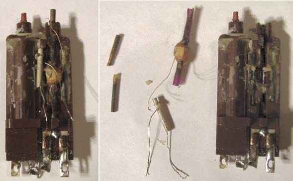
It was VERY deaf on SW. So I examined the aerial cicuit. Clipping a short wire to the Car Aerial socket was lively. Further examination revealed SW wire off centre tap of VHF choke S15 & S15' mounted under VHF Tuner section. The switch is operated by a cam pressed by inserting car aerial plug and not shown is outer coax plug connection to chassis.

Shortwave signal path from Aerial to Mixer

Coils S15 and S15' are on a single former.
I picked of the tar & wax, unpicked the two broken ends and with an extra piece of enamel wire made a new centre connection, soldered on at purple arrow. Coil ends to mount at green arrows.
Most of the time it needs an aerial wire connected to the aerial socket. 3m of wire was very lively. Later I will see if frequency is correct. VHF-FM and MW are correct. LW is slightly off.
Bias
The DF97 I have in the Oscillator position seems to be the best I have. One "safe" subsitution is to try a DF97 in the VHF mixer/osc location. One of my DF97 (which "worked" as 10.7 IF) didn't receive any VHF-FM! Perhaps I'll order a NOS from a proper dealer. Certainly ONLY put a known good DF97 in AM oscillator position and check HT current!
Tone Control
The tone control is limited in operation. No missed paper caps. There are a couple of large foil caps left, but they are not critical and also reliable Plastic Film, not paper. I swapped the DAF96, I can't say it was really a difference. My schematic showed 6.8M Ohm grid leak and 82pF grid capacitor on the DAF96 tone stage. The resistor was labelled 6.8M, but reading nearly 8M. I didn't think that would be be significant. I put 2 x 3.3M. The capacitor was labelled 56pF and measured 58pF. I clutched at straws and put 82pF. The tone pot is a little low at 1.7M instead of 2M, but the 150pF series capacitor was 152pF. I think changing the DAF96 made a slight difference and nothing else mattered. I suspect 470k in series with pot would sharpen tone a little. The pot isn't the sort easy to find a replacement. But really I don't know how "good" the tone control ought to be. Perhaps I will model it in Spice.
Switches
The band switches had a tendency to fail to latch. I removed front panel with Lamp and DM71 then re-tensioned the latch bar spring. Two "leaves" easily removed. I washed out the top area again with pressure from WD40 tube. The Push Button assembly is now working smoothly.
To thank the Author because you find the post helpful or well done.
AM, especially SW performance.
I still was not happy with AM performance, FM a little soft in tone (1.7M rather than 2M Ohm tone pot control) but AM quite poor and LW R4 fairly noisy at times. SW non-existant without external aerial.
Tone Control.
Realistically I'm unlikely to get a replacement tone control. I may try more cleaning, as these normally actually go high. Meanwhile as a temporary expedient to see if this is the issue I put 820k in series. Well, FM now goes "crisp" and tone control amount of change doesn't seem much reduced! But it's not the source of "woolliness" on AM.
I checked the two DF96, the LW/MW RF preamp/FM IF1 and the AM IF/FM IF3. The AM IF /FM IF3 really poor, with a better replacement SW performace greatly improved. But AM Audio response is still strange. Examining the AM IFTs ( 4 x brass screws, one IFT can either side of last DF96) I could see one looked disturbed. Adjustment had no effect! These IFTs use a ferrite or dust iron core (I don't know which) attached to the brass screw, an incredibly miniaturised version of the McMichael IFTs that fall apart!
When removing an IFT sketch and carefully label where the wires and parts go!
The removed IFT. 1: The wires unsoldered 2: The offending coil and core removed
I can repair it. But I swapped it for a similar part from a totally unrepairable, un-restorable, absolutely rusty wreck already missing vital parts such as scale, scale cover, Audio transformer, valve sockets, rear cover. I did briefly consider trying to restore it! But a not at all rare 1955 AM/FM table model.

Huge difference to LW noise level, audio response on AM and SW (KW) performance (sensitivity) when adjusted to 460kHz. LW tuning much sharper.
Shortwave stations now with telescopic aerial rather than external wire, though "decent" reception needs a separate aerial and/or earth.
To thank the Author because you find the post helpful or well done.