Project: Experimental Two Valve Superhet with no IF Amp.
Project: Experimental Two Valve Superhet with no IF Amp.

Now that I have your attention with the title, I should explain that this radio is a short-wave superhet covering approximately 3 to 6.5 MHz with a regenerative detector operating at 455 kHz. Technically, therefore, there is no IF amplifier, even though there is a single IF transformer.
Chas E Miller in his "Practical Handbook of Valve Radio Repair" considers this type of receiver to be "nonsense" and before I completed this radio, I would have agreed with him. There are however some reasons why this is an interesting and worthwhile project to tackle:
1. It uses readily available parts. (No hard-to-get valve IF transformers.)
2. It uses home-made tuning coils throughout.
3. It can be used as an example of ganging and tracking in a superhet.
4. It can be made in a single weekend (unlesss you want it to be a thing of beauty)
5. While winding your own coils, you can identify with the pioneers of radio and
6. the set works surprisingly well.
The idea behind this radio was simply to provide a design that could be used for instructive purposes - to make people think and perhaps enjoy experimenting with their own variations and improvements to the project presented here.
Circuit Diagram
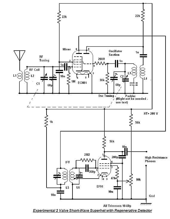
The circuit diagram will be made available in PDF format.
Principle of operation
In a superhet, the local oscillator produces a signal which is combined with the incoming signal in a mixer stage to produce an intermediate frequency. The intermediate frequency is normally amplified by one or more stages before being demodulated or detected to convert it to an audio signal.
This is a superhet radio designed to cover a frequency range of 3 to 6.5 MHz, with a little overlap at each end of the scale. The intermediate frequency is set at 455kHz, and the local oscillator is set to be above the signal frequency. As an example, suppose we want to receive the BBC on 3.255 MHz. The local oscillator must then run at 3.710 MHz (3.710 - 3.255 = .455 - the intermediate frequency). In this radio, there is no IF amplifier stage. Instead, the intermediate frequency is detected directly using a regenerative detector.
One of the first radios to use this principle was the "super-gainer" of the 1920s. In the super-gainer, not only was the detector regenerative, but the mixer stage also. It must have been a difficult set to operate! Later, there was the Cossor 348 of 1936 vintage. This used a regenerative detector for long and medium waves, and used a superheterodyne converter for short waves. The most recent set using this principle is the "regenerodyne" of Gary Johanson (WD4NKA). This set uses a tunable intermediate frequency behind a crystal-controlled superheterodyne converter. This principle is well suited to amateur band only reception.
In the set described here, the input signal is tuned by L2/C1 and is applied to the control grid of the ECH81 heptode section. The local oscillator signal is tuned by L3/C2 and mixes with the input signal to produce the intermediate frequency at the ECH81 anode pin 6. This is tuned by the primary of the intermediate frequency transformer and coupled to the detector input tuned circuit L6. The regenerative detector is an EF91,a valve commonly used in military equipment of the late '40s and early '50s. The detector design was inspired by a circuit in FJ Camm's "Practical Wireless Circuits" (Newnes, 1968). Reaction is obtained from the cathode tap on L6 and the potentiometer in the screen grid controls regeneration.
The triode of the ECH81 operates as a tuned grid oscillator, the 200 Ohm resistor in the grid circuit is used to improve oscillator stability.
In this set, the reaction should in theory be a pre-set control, so it is not available on the front panel of my initial design. If you are planning to receive SSB signals, you may want to advance the control to the point where oscillation just occurs. The hope is that the detector stage will oscillate at the intermediate frequency and replace the missing carrier from the SSB signal. It works, but is a very fiddly operation.
As it stands, the set produces plenty of volume into a crystal earpiece. It might be tempting to add an ECL82 (6BM8) audio stage to drive a loudspeaker.
The set operates best at an HT voltage of 200 volts. It will operate from 150 to 250 volts
IF Transformer
Imagine a world where iron dust cores don't exist and all tuning coils have to be air-cored - even IF transformers. The only way to adjust tuned circuits to the correct frequency is 1. remove turns 2. use a tuning capacitor. Because nowadays everything is digital, we are almost back to that world. I believe there are a few specialist firms that produce IF transformers and coils for valve equipment - but there are certainly none in my part of the world. (There is a shop here in Johannesburg with boxes and boxes of transistor IF transformers of all shapes, sizes and frequencies. I think some of them would work in a valve circuit.)
To design the IF transformer, I worked out the required inductance on the assumption that it would resonate with a 100p capacitor, made up from a 60p trimmer and 40p stray capacitance. I then used one of "Wheeler's Formulae" to calculate the number of turns required, making a few assumptions about the final outside diameter of the coil(s).
All the inductances were wound using plastic pill containers as formers. These have a diameter of approximately 18mm. Based on these assumptions, the coils were given 250 turns of 46 gauge double silk covered wire. They were spaced (arbitrarily) at about 20 mm apart. The cathode tap was made at 20 turns.
The measured inductance was 1.31mH and 1.36mH - rather more than planned, but I went ahead and used the coils anyway.
60p Philips trimmers were used to tune the coils, but I had to add a 100p capacitor to the coil in the mixer anode.
The detector stage was constructed first and the alignment was set at 455kHz using a signal generator.
Note: When winding the coils by hand, don't wind them like a solenoid. The method adopted was to gradually rotate the former in one hand whilst quickly winding the wire in a criss-cross pattern with the other. The coil will have an open texture - the idea being to reduce coil self-capacitance and increase the "Q" or efficiency of the coil. I made the winding length approximately 6mm. (Or, at least, I tried to).
This is the only difficult part of the construction. The wire will kink and snarl and probably snap a few times, so a lot of patience is required.
The coil does not have to be a real "high - Q" job as for a normal superhet, because the regenerative detector will act as a "Q multiplier".
The signal and oscillator tuned circuits - padding and tracking.
In order for the set to operate over the planned frequency range, the input tuned circuit must resonate at 6.5 MHz with the tuning capacitor vanes at their minimum position (fully out) and must resonate at 3.0MHz with the capacitance at maximum. The oscillator tuned circuit must resonate at 6.955 MHz at tuning capacitor minimum and must resonate at 3.455 MHz at tuning capacitor maximum. These two frequencies should keep in step or "track" throughout the entire tuning range of the receiver.
In this receiver, we also want to restrict the possible tuning range. This is done by effectively reducing the swing of the tuning capacitor by adding capacitors in parallel. These are the trimmer capacitors and fairly obviously will reduce the percentage change in capacitance compared to the total. In addition to the trimmer capacitors, there will be stray capacitance from the wiring, the valve, etc.
In a superhet with the local oscillator running above the signal frequency, the swing of the local oscillator capacitor needs to be less than the swing of the signal frequency capacitor because the inductance of the local oscillator tuned circuit is smaller. For example, with the both capacitors at the minimum position, the capacitance across the tuned circuits will be almost the same, but the the local oscillator frequency will be higher - so less inductance is required. Since the inductance is smaller, the tuning capacitor must be smaller to achieve the same change in frequency as the signal circuits.
Normally capacitors are made with the same capacitance for each section and a padder capacitor is added in series with the local oscillator capacitor to reduce its swing.(This was explained in the forum article here). In this radio, the tuning capacitor has unequal sections. The signal section measured 410pf and the oscillator section measured 360pf. This is rather like having two sections of 410pf with a 3300pf padder.
The method used to calculate the inductance, padder and trimmer capacitors was that given in the "Radio Designer's Handbook", Langford-Smith, (Fifth Edition, Iliffe, 1960).pp 1002 and following in an article by B.Sandel. In days gone by, these calculations would have been carried out by hand, perhaps using a slide rule. Fortunately we have computers these days. The result of the calculation was that I should use a 3300pf trimmer with 5.56uH signal frequency inductance and 4.70 uH local oscillator inductance. Trimmers should be 70p and 30p. Calculations were done using a homemade text-editor program with arithmetic capability called CalcPad2, which runs under Windows XP.A check on the tracking was performed using a another home written program. These are all available from me at no cost.
The fact that the calculations gave a padder value the same as the value required to pad a 410pf capacitor down to 360pf is probably not a coincidence. Be that as it may, it is certainly convenient.
Using the Wheeler formula for a close wound air-spaced coil yielded values of 19 turns and 17.6 turns over a 12mm length. Both coils were wound to 20 turns. (See "alignment"). Coupling coils for oscillator and aerial were each made 4 turns.
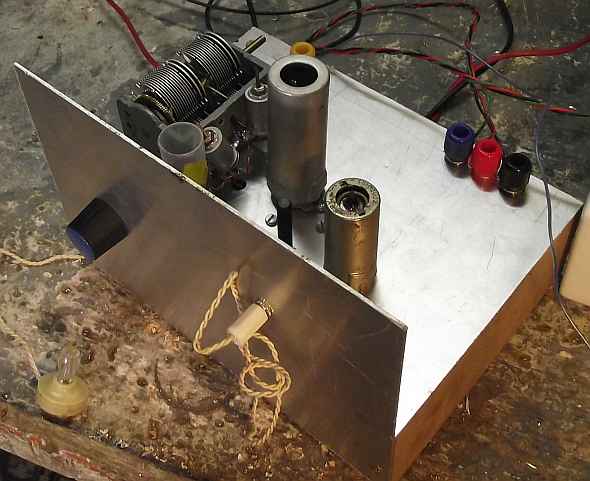
Construction
The set was made on a chassis made from a piece of 18 SWG aluminium alloy measuring 180mm x 160mm screwed to two rails of supawood measuring 50mm x 160mm x 10mm thick.
The tuning capacitor was mounted at the left edge of the chassis with a hole for the B9A base 90 mm from the left edge and 60mm from the front. The B7G valve base for the EF91 was placed 60mm from the right edge, 40mm from the front. "Left" and "right" are as viewed from the front. A long tagstrip was mounted diagonally between the two valveholders, and another near the ECH81 local oscilator coil.
The coils were fitted to the chassis with self-tapping screws and all coil windings were held in place with "RS" tropical varnish. (I used to make my own coil cement from clear ball-point pen cases dissolved in laquer thnners).
Whenever I build radios, I do so from the back to the front - first the audio stages, then the detector then the IF and so on. This way its easy to test everything works before going further. In this case, I began with the detector. No problems were experienced and the detector was tuned to 455 kHz.
The next section was the local oscillator. This was wired in accordance with the circuit diagram and checked before applying power. I tuned a short-wave radio to the (hoped-for)local oscillator frequency -- and heard nothing. After correcting my mistake in the wiring, the local oscillator was again checked and worked throughout the tuning capacitor swing. If the oscillator refuses to work, try reversing the coupling coil connections.
Finally the mixer stage was wired and checked by applying a signal generator near the grid at about 4MHz. At this stage, we have a working, but badly adjusted radio.
Soldering
Many constructors like to follow the principle of wrapping the component wires round the tags, carefully routing heater connections with a twisted pair and so on (see books such as the RSGB handbook for how to do it properly.) I notice that some manufacturers (Eddystone, Tektronix) seem to follow the principle of merely placing the component either on or through the tag-strip and soldering it without wrapping. If you do this, then you have to be sure that the parts to be joined are properly tinned and wetted by the solder to ensure a good joint. The advantage of this type of soldering is that you can easily remove and replace parts and correct errors as you go.

Whichever method suits you, be sure to check every joint and take extra care to to do another check before applying power.
Alignment
The first step is to adjust tuning coil in the mixer anode. This was done by applying a signal of 455kHz to the grid of the ECH81 and then by adjusting the capacitance across L5 for maximum signal from the detector.
Next, the local oscillator is adjusted. With the trimmer capacitor at mid-position and the capacitor at maximum, remove turns until the local oscillator is operating at about 3.455 MHz. (Don't get too fussy - 3.2MHz is near enough). Now with the tuning capacitor at minimum, adjust the trimmer so the local oscillator frequency is about 7 MHz. I used a short-wave radio tuned to the local oscillator frequency, but a frequency counter might be easier.
Finally, the signal frequency circuit is adjusted. With the set tuned to receive 3.2MHz and the signal frequency trimmer at mid-position, remove turns until the signal is at a maximum. Now set the signal generator to 6.5MHz and trim the signal for maximum using the trimmer.
Power Supply
The set was operated from a power supply providing 6.3 volts for the valve heaters and a variable HT supply capable of providing 0 to 250 volts.
The valve heaters can be wired in series and a 12 volt transformer can then be used. The set draws about 20mA, so a small 10 watt (for safety) 200-0-200 volt transformer can be used with two 1N4007 diodes and a 100u smoothing capacitor.
Operation
My first impression using my workshop antenna (5m of wire running up a chimney) was not very favourable. The set worked and picked up all the stations targetted, but not too great. Then I remembered, some of my recent repairs using the same aerial weren't that spectacular either. I then attached the chassis to a proper ground and the aerial to a 20m long wire. With this set up, all the short-wave stations available on my communications receivers were audible on this set. Unfortunately, this included the PLT/ADSL interference that seems to pervade the air waves locally.
The tuning capacitor I used had a built-in 6:1 reduction gear, but this is not really good enough, particularly if you are attempting to resolve SSB.
Normally, the set should be operated with the reaction control backed some way off the point where the detector breaks into oscillation - probably a bit further than you normally operate a regenerative receiver. There should still be some aerial noise. Now you can operate the set just like a normal superhet and forget about the reaction control. If you back the control too far - you will get too much bandwidth and too little gain. Push it too far and the bandwidth will be too narrow and the gain might cause strong stations to overload the set. (This set has no AVC).
Conclusion
I call this an experimental set, because I present it as a springboard for your own ideas. Maybe you want to make an antique-looking radio (my construction was quick and a bit horrible). Maybe a transistor version. Perhaps you want to make a similar set covering other wavebands. How do you think AVC could be applied ?
I eventually abandoned the crystal earpiece and now play the set through my PC sound card.
To thank the Author because you find the post helpful or well done.