tektronix: R7912; Transient Digitizer
tektronix: R7912; Transient Digitizer
Source: Tektronix R7912 Transient Digitizer Service Manual
THEORY OF OPERATION
Introduction
The R7912 Transient Digitizer allows extremely short rise-time signals to be acquired, converted to digital format, and stored in a local memory. Its operation appears at first to be like that of an oscilloscope, but the similarity is slight. Like an oscilloscope, the R7912 accepts a variety of input signals through conventional 7000-Series plug-in amplifiers. The signal is used to vertically deflect an electron beam as it is swept horizontally under control of the time base plug-in. The similarity ends there.
The Scan Converter
Instead of the usual phosphor-coated CRT found in an oscilloscope, the R7912 uses a specially designed tube called a Scan Converter (see Fig. 3-1). The Scan Converter tube has a small silicon diode target at its center. The electron beam, deflected by the time base plug-in and the amplified input signal (called the writing beam), is swept across this target.

Fig. 3-1. The R7912 Scan Converter tube.
The Target
Composed of an array of silicon diodes on a single chip 1.3 cm by 0.95 cm, the target has a diode density of about 800 diodes per linear centimeter (see Fig. 3-2).
This target diodes are formed by diffusing a p-type material into an n-type substrate. The side of the target containing these diffusions faces a reading gun that continuously scans the diode array with an electron beam. This electron beam is referred to as the reading beam, and it deposits a charge on the target surface. The deposited charge causes the target diodes to reverse bias and charge toward the cathode potential of the reading gun. In the charged condition, the target diodes are in an unwritten state.

Fig. 3-2. Scan Converter diode target.
Writing a Trace on the Target
The writing beam, carrying the information from the plug-ins, traces an image of the waveform on the back side of the target. Bombardment of the target by the intense writing beam creates electron-hole pairs near the substrate surface. The holes diffuse across the substrate to those diodes opposite the writing beam, causing them to lose their charge. This discharged condition is the written state.
Reading the Target
The reading beam reads the waveform image by recharging the written diodes while it scans the target. Each time the reading beam recharges an area of written diodes, a signal current is generated in the target lead. The operational mode of the R7912 determines what this signal current is used for.
TV Mode
When the R7912 is in the TV mode (NON-STORE), the reading beam scans the target in a horizontal format similar to that used in conventional television systems. The target lead signals obtained while reading in this mode are used to generate video output compatible with television monitors such as the Tektronix 632 Picture Monitor. The TV monitor provides an immediate display of the written trace, and is of great value during initial "setup."
Digital Mode
The Digital mode is of primary importance when operating the R7912 with a computer. In this mode, waveforms are converted to digital information, stored in a self-contained memory, and made available to the computer.
In the Digital mode, the reading beam scans the target vertically. Each vertical scan consists of 512 discrete steps down the target. After each vertical scan is complete, the reading beam retraces to the top of the target and advances one step horizontally. There are 512 horizontal steps across the target (see Fig. 3-3). This scanning technique produces a 512 X 512 matrix of addressable areas on the target.

Fig. 3-3. Target scanning in Digital mode.
After each vertical scan is complete, and during the time the reading beam retraces to the top of the target, a binary word is issued by the horizontal address counter. This binary word indicates the horizontal position of the next vertical column to be scanned by the reading beam.
Digitizing the Trace
As the reading beam steps down each vertical column, it pauses at each step for about 100 nanoseconds. The circuitry determines whether or not the diode area under the beam has been written. If the area is unwritten (no target lead signal), the beam steps down to the next addressable area on the target. The step from one unwritten area to the next also takes about 100 nanoseconds.
When the reading beam steps into a written area of the target, the beam recharges the written diodes, producing a target lead signal. The signal causes the reading beam to pause for 1.6 microseconds while a binary word describing its vertical position on the target is issued. The delay allows the vertical word to be stored in the R7912 memory.
Since the writing beam is of finite diameter (approximately 0.02 millimeter), it covers more than one target diode at any given time. Indeed, the target diode density is such that the beam covers several diodes wholly, and several more partially. Writing beam intensity, as controlled by the front-panel INTENSITY control, also affects the number of diodes discharged.
The finite beam diameter results in a trace that may be several vertical addresses wide. As the reading beam steps downward across the discharged trace image, the lead signal maintained.
To prevent vertical addresses from being issued at every vertical position throughout the beam thickness, only the rising and falling edges of the target lead signal are detected. A diagram of the reading process is given in Fig. 3-4. Note that the data is issued in the following sequence: horizontal word - vertical word - vertical word; next horizontal word - vertical word - vertical word, etc.
Storing the Data
A sweep trigger begins the memory loading process in the R7912. In Single-Sweep mode, the trigger by itself is sufficient, but in Repetitive-Sweep mode, the trigger must be preceded by a Load Memory command. Figure 3-5 describes a memory load cycle for both sweep modes.
Since the reading beam operates continuously, the point on the target where storing begins is dependent upon sweep speed, waveform repetition rate, and Load Command timing. As a result, the first horizontal address stored may be any of the 512 addresses on the target. The vertical words associated with that horizontal are stored next, followed by the next horizontal word. Reading and storing continues until the first column read is reached again. After all waveform data are stored, the R7912 requests interrupt. Address strap options in each R7912 indicate to the controller which instrument has data, and a service routine can be initiated.

Fig. 3-4. Reading the diode target

Fig. 3-5. Normal operating sequence
Vielen Dank an Herrn Dietmar Rudolph, der meine Bilder nachbearbeitet hat.
To thank the Author because you find the post helpful or well done.
A new way to look at transients
A new way to look at transients
 |
The display and analysis of fast, single-shot Incises has long been one of the most challenging problems in oscillography. These pulses result from measurements in a wide variety of fields such as laser research, nuclear research, computer design and service, stress analysis of components, and others. In the past, the only way to view fast transients, which may be a nanosecond or less in duration, has been to use an oscilloscope with a viewing hood or the very best scope/camera combination. These methods have been quite successful as proven by the many thousands of TEKTRONIX Oscilloscopes in installations of this kind, but there are some obvious disadvantages. |
One is the need to dark-adapt one's eyes before attempting to view a fast transient. Another is the time required to develop and analyze the photograph containing the waveform. Still another is the expense and inconvenience of using film, particularly when the waveforms need to be digitized for computer processing. Many of the present methods for digitizing waveforms from film involve hand processing with resultant time-consuming delays and possibility for errors.
The TEKTRONIX R7912 -Transient Digitizer solves these problems in a unique and novel way, and in addition, provides features not available on earlier instruments. "The functions of writing and reading, which in a normal oscilloscope are carried out by the same CRT beam, are accomplished by two separate electron beams in the R7912; waveform display is handled by a third beam in an associated monitor. This allows optimizing the design of each function to achieve the overall goal of large, bright, high-resolution waveform displays. The waveform can be displayed on a TV monitor such as the TEKTRONIX 632 to provide a bright, large-screen display easily viewable in room-ambient light: equivalent photographic writing rate in this mode is 30,000 div/µs. In addition, the waveform can be automatically digitized: i.e., the waveforms arc processed into a computer-compatible format so they can be analyzed by a computer. Or, if desired, the waveforms can be stored in a self-contained memory (optional) and displayed on an X-Y monitor; an equivalent stored writing rate of 8,000 div/µs can be achieved with no limitation on storage time. (If display area is 8 by 10 centimeters stored writing rate is equivalent to 8,000 cm/ µs.)
Instrument Description
Fig.1 shows a block diagram of the instrument. The writing section of the R7912 is similar to a conventional oscilloscope. "The input signal is acquired, conditioned, and amplified by vertical plug-ins front the TEKTRONIX 7000-Series family. Any of the 7A-Series plug-ins can be used, allowing a wide choice of vertical capabilities from high gain (as low as 10 µV/div with the 7A22 Differential Amplifier) to maximum bandwidth (1 GHz with the 7A21N Direct Access Unit). Horizontal sweep and sweep gate are generated by a 7B-Series time base plug-in.
The input signal is applied to the CRT writing gun. Design and operation of the CRT is described in a special feature section of this article. The waveform written on the target by the writing gun is read out by the reading gun. With the instrument operating in the NON STORE mode, the reading beam scans the target linearly in a TV format and operation is quite similar to that of a conventional TV camera. Each time the reading beam crosses a written point, a small current pulse is generated in the target lead. This pulse is amplified and processed to provide the video output signal.
Synchronizing signals for the Read System and the associated video monitor are generated by the Sync Generator. The X and Y Ramp Generator and Scan Amplifier produce the waveforms required to drive the X and Y deflection plates of the Read System.
In the DIGITAL mode, the read sequence is changed while the write sequence remains as already described. In this mode, the target is scanned in steps in a 512 by 512 matrix rather than linearly. Also, fast scanning occurs vertically in the DIGITAL mode which is opposite to the NON STORE mode where fast scanning is done in the horizontal direction as in conventional TV. Fig. 2 illustrates these two scan modes using simplified waveforms and scan lines. The NON STORE mode, being similar to conventional TV, will not be explained further here.

Fig1. R7912 Block Diagram.

Fig. 2. Target scanning modes.
Vertical scanning is used in the DIGITAL mode due to the nature of the waveforms normally digitized. Notice that for the simplified scan shown in Fig. 2B, each vertical scan line intersects the waveform only once. In this mode, addresses of points on the target are transferred and stored in memory only when a trace has been written at that point on the target. This results in the fastest readout of information needed to define a waveform, and requires less storage space in memory for the waveform. In actual operation, the trace is several samples wide and circuitry is incorporated in the instrument to reduce the amount of information which must be communicated to define a trace. The counters and logic circuits required for digital operation are contained in the Logic circuit. The optional Memory allows waveforms to be stored in the DIGITAL mode for later transfer to a computer, or for display on a storage display unit through a display interface.
The R7912 uses the CRT READOUT SYSTEM pioneered in the TEKTRONIX 7000 Series to display measurement parameters along with the waveform. These characters are written on the diode target by the writing beam on a time-shared basis and become part of the output signal in the NON STORE mode. An optional converter is available for use in the DIGITAL mode to take the readout information directly from the plug-ins and convert it into an ASCII coded format which becomes part of the data communicated to the computer.
The optional Electronic Graticule Generator produces a clot array similar to the graticule on a conventional oscilloscope CRT. The electronic graticule is written on a time-share basis with the input signal and, like the CRT READOUT signal, becomes part of the output signal from the Read System. This electronic graticule eliminates parallax associated with overlay graticules and minimizes errors due to non-linearities or drift in the amplifiers or CRT deflection system.
Novel Circuitry – The Key to Perform
As you would expect in a state-of-the-art instrument, many novel circuits make up the R7912. These include a highly stable - 10 kV power supply, an electronic graticule generator, low-noise amplifiers, and unique logic circuits. Let's look at several of these circuits in more detail.
Ramp Generator. A block diagram of the Ramp Generator is shown in Fig. 3. Two of these circuits are used in the R7912: one for the vertical and one for the horizontal. In the NON STORE mode, the Integrator generates a highly linear ramp (waveform A) whose amplitude is precisely set by two stable discriminators which define the upper and lower end points of the ramp. This waveform is synchronized by the action of the Phase Detector which compares the end of the ramp with the sync pulses. If there is an error, it changes the timing, or charge current, of the integrator to insure proper timing.

Fig. 3. Ramp Generator.
In the DIGITAL mode, 5-MHz clock pulses are connected to a Single-Shot Multivibrator and to a / 512 Counter. Each time the Multivibrator fires, a small amount of current is injected into the Integrator, resulting in a step at its output. The voltage of the output step remains stationary during the Multivibrator's quiescent period. After a number of ramp and hold steps have been accomplished, the Upper Threshold Discriminator resets the End-Of-Ramp Flip Flop causing the integrator to reset. The circuit is then ready to produce a new staircase waveform. The output of the End-Of-Ramp Flip Flop and the / 512 Counter are compared by the Phase Detector. If these pulses do not occur simultaneously, a correction signal is generated by the Phase Detector and the charging current of the Integrator is suitably adjusted. In this fashion, the Phase Detector insures that precisely 512 steps are generated for each vertical or horizontal scan, resulting in a stable digitized waveform.
One of the features of this circuit is that the period of the staircase can he changed without affecting the accuracy of the staircase. This occurs in the operation of the R7912 when a point is addressed on the target where a waveform has been written. Normally, the staircase holds at each step for about 100 nanoseconds while the signal on the target lead is checked for a change in state since the previous sample. If there is no change, the staircase is advanced to the next step. However, when a change is detected, the staircase holds at this step for about 1.6 microseconds to allow time for the address of this data point to be transferred to the computer or stored in memory. As a result, each staircase may have a different duration since the number of these pauses for address transfer will vary depending on the nature of the waveform written on the target. In a conventional feedback-stabilized circuit, this would result in timing variation and an inaccurately digitized waveform. To prevent this, the clock input pulses are interrupted during the address communication time. Both the Single-Shot Multivibrator and the 512 Counter remain inactive until the clock resumes. Highly stable circuitry in the Integrator holds the step level very constant during the pause. The overall result is that when normal operation resumes, the outputs of the End-Of-Ramp Flip-Flop and the / 512 Counter have been delayed by the same amount of time. Therefore, no error signal is generated at the input of the Phase Detector and the ramp generator remains stable and phase locked even though the period of the staircase has changed.
Each of the vertical and horizontal steps has a BCD - coded address associated with it which is stored in the optional memory or transferred to a computer when valid waveform data is detected on the target. Both a vertical and a horizontal address is required to define a point on the target. Since the dot raster is a 512 by 512 matrix, there are over 250,000 addressable points on the target. The average waveform normally requires about 1500 points for complete definition. However, under some conditions such as dual-trace operation, two waveforms may he stored in memory simultaneously. To provide adequate storage, a 4000-word memory has been provided as an option for the R7912.
Electronic Graticule
Another interesting circuit is the Electronic Graticule Generator as shown by the block diagram in Fig. 4. This circuit generates all of the information needed to write the graticule on the target, along with the waveforms and readout. At the end of each sweep, this circuit is activated to begin producing the graticule. The master clock signal provides a precise reference for accuracy; all output signals are derived from the clock.
The electronic graticule is defined on the screen by a series of dots 0.2 division apart for the minor divisions and 1 division apart for the major divisions. When the electronic graticule is activated, fast ramps are produced in the vertical direction. Since the first ramp at the left side of the graticule must define both the major and minor divisions, 41 dots must be displayed to produce eight major divisions. During this ramp the master clock input is connected directly to the Dot Multiplexer which produces one Z-Axis intensifying pulse for each clock input.
The Vertical Dot Counter (/ 45) produces an output after 45 clock pulses, which serves as a reference to the phase-locked Vertical Integrator. Operation of this ramp generator is similar to the Ramp Generator described previously. As the vertical ramp is reset, it triggers the Horizontal Staircase Generator which moves the next trace one step or 0.2 division to the right. At the same time, the output of the Major Division Counter (/ 5) changes state, causing the Dot Multiplexer to switch from the direct vertical clots input to the Vertical-Dots-Divided-by-5 Input. During this vertical ramp, a dot is displayed every fifth clock pulse to define a major division.

Fig. 4. Block diagram of Electronic Graticule Generator.


Fig. 5. Performance of R7912 (top waveforms) compared to fastest conventional oscilloscope (bottom waveforms) . No waveform is shown for the conventional oscilloscope at 2.4 GHZ since it could not display this signal.
Three more vertical ramps are generated in this manner. Then, the output of the Major Division Counter switches so that dots are again displayed every 0.2 division. Action continues until the graticule is complete. When the Horizontal Counter (/11) has received 11 inputs from the Major Division Counter (/5) the graticule is complete and it resets the Graticule Gating Flip Flop. This action turns off the Graticule Control block and halts operation of this circuit. About four milliseconds are required to write the complete graticule.
The Proof Is In The Performance
Performance of the instrument is best shown by the accompanying photographs. Fig. 5 shows continuous sinewave signals as displayed by both an R7912 Transient Digitizer/ TV monitor (NON STORE mode) and a TEKTRONIX 7904 Oscilloscope. Identical plug-ins were used for both measurement systems. Fig. 6 shows the reconstructed display of a single pulse that was digitized by the R7912. The digital information was fed to a computer through the instrument's optional memory and interface circuits. It was then re¬constructed and displayed on a TEKTRONIX storage display monitor.
Acknowledgments
This instrument, as many state-of-the-art projects, is the result of the dedicated effort of many people. These include: Carlo Infante, Program Manager; Jim Cavoretto, Project Engineer who also provided valuable assistance in compiling this article; Al Allworth, Don Roberts, and Stu McNaughton, Electrical Engineers; Walt Lowy, Engineering Technician; Ray Hayes, Ken Hawken, Bob Culter, Hal Cobb, Ed Ritz, and Bo Janko, CRT Engineering; Loyal Strom, Helene Albright and Ken Nesvold, Prototype Support; Doug Giesbers, Larry Pearson and Phil Lloyd, Mechanical Engineering; Nick Hughes and Ray Blohm, Instrument Manufacturing. The list would not be complete if special recognition were not given to these marketing people whose inputs and support were always very valuable: Bob Hightower, Bob Johnson, and Bill West.


Fig. 6. Digitized waveform, reconstructed and displayed on a TEKTRONIX 603 Storage Monitor.
A close-up look at the crt
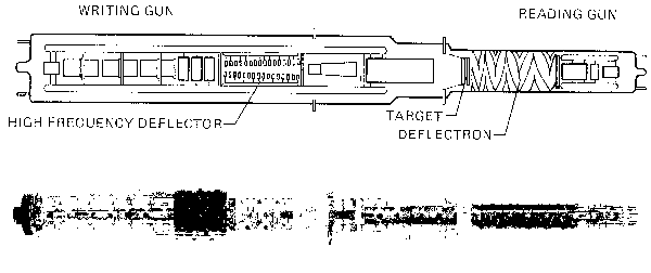
Fig. A. R7912 CRT.
The outstanding performance of the R7912 is clue, in large part, to the TEKTRONIX-developed scan-converter tube forming the heart of the system. Fig.A shows a drawing of the tube along with a photograph of the final product. The tube is double-ended with the write gun and read gun facing each other axially. These guns and their associated deflection structures are separated by the target, where scan conversion occurs. The design parameters of the tube were optimized by means of a computer program to pros isle the best trade offs in gun structure and accelerating potential for the required resolution and scan area at the target.
"The input signal from the vertical amplifier is applied to the high-frequency deflector which consists of two helical delay lines assembled into a balanced deflection system. "The entire writing-gun structure is operated at —10 kV to provide small spot size and fast writing rate.
'The target consists of an array of diode junctions formed on a silicon wafer using integrated-circuit techniques. Fig.B shows a detailed view of the silicon target. A density of 2000 diodes per inch yields the desired resolution for the ½ by 3/8 inch scanned area. The center 0.75-inch diameter of the target is thinned to about 10 microns to facilitate operation in the double-ended mode (by comparison, the thickness of this page is about 100 microns).
The react gun produces a low-velocity electron beam with minimum shading and good resolution. Shading is caused by off-normal landing of the beam on the target and results in errors in the readout signal. This is particularly objectionable in a precision measurement instrument such as the R7912 and becomes even more of a problem when the output signal is converted into digital form (see Fig. C).
To accommodate the variable scan rates required of this instrument, electrostatic deflection was chosen for the read gun rather than the electromagnetic methods normally used for vidicons. However, if electrostatic focusing is used along with electrostatic deflection, poor shading characteristics result.
|
|
For a complete discussion of the design considerations that went into the CR'T for the R7912, refer to "Storage Tube With Silicon Target Captures Very Fast -Transients" by Raymond Hayes, Robert C. Cutler, and Kenneth W. Hawken, Electronics, pp. 97-102. Aug. 30, 1973. |

To solve these problems, a hybrid design was developed consisting of an electrostatic deflection system surrounded by an axial magnetic focusing field. The deflection plates actually consist of a cylindrical electrode pattern photo-etched on the interior wall of the tube (see Fig. A). The axial magnetic field is provided by an external solenoid. This configuration is called a deflectron deflection system2
As the reading beam is scanned across the target, it charges the target negatively towards the read-gun cathode potential and the target diodes are reverse biased. High-velocity electrons from the write gun bombard the back of the target, creating electron-hole pairs which diffuse through the target. This causes the diodes to conduct and discharge in the written area. When the reading beam next scans the written area, it recharges the diodes, producing a signal current in the target lead. Amplification and processing of this signal provides the video or digital output signal.

Fig. C..Effects of shading on digitized video.
2For a complete discussion of the deflection system, see "Electron Trojectories in Twisted Electrostatic Deflection Yokes" by E. F. Ritz, IEEE. Transactions on Electronic Devices, November I973.
Source: TEKSCOPE 1973
The Tektronix 7912AD and the 7912HB uses the same tube as the R7912
Attachments:
To thank the Author because you find the post helpful or well done.