WD-11 Tube Adaptor & Template Mold
WD-11 Tube Adaptor & Template Mold
WD-11 TUBE ADAPTOR & TEMPLATE MOLD
TUBES FOR SUBSTITUTION:
The WD-11 Tube was introduced by Westinghouse in 1922 for their Aeriola, Sr. (Model-RF). What they needed was a tube which could be heated with dry cells instead of storage batteries. The WD-11 was also used in the RS, Regenenoflex, RadiolaX, Radiola III and the Radiola III-A. The WD-11 filament structure was very fragile. When it burned out there was a real possibility that it would short against the plate thus applying B+ to the filament circuit with disastrous results. 1924 was the last time the WD-11 was used in production thus it became obsolete very quickly. Today, 90 years later, these tubes are very difficult to obtain and if one can obtain them, they are very expensive.
Following are substitute tubes that would fit the following criteria; Tubes that are fairly readily available, tubes that are not priced too prohibitively, tubes that come close to the specifications of the WD-11 but would still work well.
TUBE Fil. V/A Bias V. Plate mA Gm u Base
WD-11 1.1 .25 -4.5 2.8 400 5.6 Unique
1Q5 1.4 .10 -4.5 5.8 1075 7.8 Octal
1A5 1.4 .05 -4.5 5.6 1070 8.0 Octal
1LA4 1.4 .05 -4.5 5.5 1065 8.1 Loctal
RCA recommends that the Radiola III-A be operated with 22.5 V on the detector and 90V with -4.5 bias on the three amplifier tubes. Accordingly, the transfer characteristics of the WD11 and the three above substitutes were examined at Ep=90V.
The following graph results show the WD-11, 1Q5 and 1A5 having long linear transfer curves. The 1LE3 has a much narrower operating range. The steeper slope of the 1Q5 and 1A5/11LA4 reflect their higher trans-conductance. These three tubes have similar amplification factors (u).

Reference 1
TEMPLATE MOLD CONSTRUCTION:
Tube number, 1A5, was selected for use with my, Radiola III-A, and the article.
Tools required to build the template mold & adaptor others will be shown as we proceed.

CALIPERS: --- DRILL BITS; a good quality bit is recommended.
COUNTERSINK; if you do not have a countersink a larger drill will take its place.
SANDING DRUM; I was using a 3/4" and a 2 1/2" one.
UNIBIT --- must have a 1" cutter on it, I believe a #5 unibit would fit the bill.
DOWEL PLUG & TENON CUTTER; The picture shows a carbide tipped cutter but a stainless steel one is also available. I have used both and find the carbide tipped one does a better job. (See Resources at the end for more details)
The tools shown and the tools used, as we progress, are not necessarily the only tools that will perform the job. Use the tools that you have and are comfortable with.
Supplies required:

BRASS TUBING; 4 different sizes required.
SPRINKLER HEAD; used for the template molds outside tubing.
BLACK ACRYLIC PLASTIC SHEET; (Plexiglas) 3/16" to 1/4" thick and approximately 6" x 8". It seems that it is manufactured in 0.177" sheets, which I used.
(See Resources at the end for more details)
At first tried making the tube adaptor by using simple measurements on a piece of plexiglas and then drilling the Plexiglas and cutting it round. But found, even very minor inaccuracies in the measurements and drilling holes put the pin placement out enough that it did not fit the tube socket at all. Thus, a template mold was constructed using the WD-11 tube base for the template mold; accuracy was therefore obtained for each adaptor produced. The WD-11 tube was well worth the expenditure. Display or non-functioning, WD-11's, are available on the internet and if one does some shopping they can be purchased for a reasonable price.

Construct the brass guide pins out of the following Brass Tubing. Stock for the 1/8" guide pins 3/16" / 0.1875" OD x 0.03" wall x 0.1275' ID. and stock for the 3/16" guide pin 1/4" / 0.25" OD x 0.03" wall x 0.19 ID.
Cut 3 pins 7/8" long from the 3/16" OD brass tubing and 1 Pin 7/8" long from the 1/4" OD tubing. Smooth off the ends and make them square. Drill the (3) 3/16" OD pins out with a 1/8" drill and drill the (1) 1/4" OD pin out with a 3/16" drill.


What we want to happen, is have the pins slide smoothly over (off and on) the tube pins. You might have to use a little side to side pressure with the drill to enlarge the holes in the brass tubing for them to slide nicely over the tube pins. They cannot be tight or you will not be able to slide the tube off the template mold when the mold is completed.

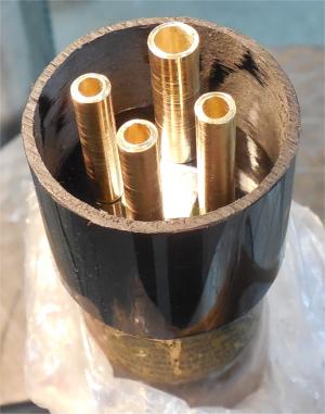
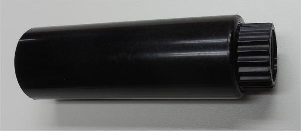
Sprinkler Head; Take it apart and save the outside tubing that has the threads on one end and a ridged top on the other end. Cut off the threaded end. Be sure all the cuts are square. On the same end as the threads were on, Cut a 1 1/16" piece off of the tube. This will be used for the outside ring of the adaptor. Do not throw away the piece of tubing with the ridged end on it. (See the supplies picture)
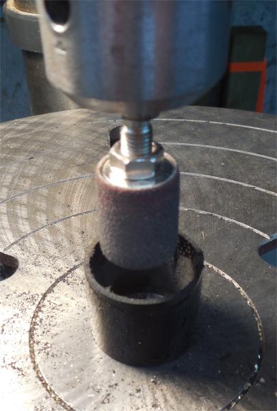
The inside of the tubing has 6 ridges running lengthwise in it. Remove these ridges on the 1-1/16" piece you have just cut off. A drum sander does a nice job.
On the piece of black Plexiglas scribe a 1 1/4" diameter circle. You will want to use a large enough piece of plexiglass to be able to clamp it down, on the drill press table, so it will not move or shift, when the 1-1/4' circle is cut out. Scribe the diagram on the Plexiglas as shown on the diagram; measure, mark, center punch and drill the (3) 1/8" holes and the (1) 3/16" hole. Also, center punch the centre of the disk. Be sure the plexiglas is clamped down so it will not move when drilling the holes. Start out with a small drill and work up to the size that is required. Good quality drill bits are recommended.

See Reference 1.
When you are finished drilling the holes, the tube should slide into them smoothly. If not, you will have to enlarge the size of the hole(s) so the tube will slide all the way into them smoothly. If they are not, you will have to use a slightly larger drill bit or use a little side to side pressure with the drill bit to make the holes larger or oblong.
Use the, Dowel Plug & Tenon Cutter, to cut the 1 1/4" disk out. Line up the cutter exactly on the circle you drew and then clamp the sheet of plexiglas securely to the drill press table. Now cut the circle out.

Some WD-11 tubes have a small extruding tip on their base in the centre of the pins. If yours does, you will have to countersink a hole to accommodate it, so the disk will fit flat on the base. If the hole goes completely through the disk you must cover it with some type of tape to stop the epoxy filler from going through and contacting the tube base. If it does, contact the tube base, you will have a problem removing the tube from the mold.


The disk, when finished, has to fit smoothly over the WD-11 tube pins and must fit flush to the bottom of the tube base. Again, the disk must slide smoothly on and off the tube base or you will not be able to slide the tube off the mold when it is finished.


Insert the disk into the 1 1/16" long piece of tubing far enough to leave a 3/16" lip between the end of the tubing and the disk. The disk should fit fairly tight. This is where the blank disks will fit when the adaptor is being made. If the disk is too large, it will have to be slightly sanded down, but should be a fairly tight fit. Now, slide the tubing, with the disk installed, over the tube pins so the base of the tube is resting on the disk. Be sure the 3/16" lip is still over the tube base and the base of the tube is squarely touching the disk. Wrap some tape around the tubing and tube base to hold it in place.


Fill the tubing around the pins full of epoxy filler and let it cure. Be sure the epoxy filler does not touch the actual tube pins or base.


When the epoxy has hardened, drill a hole approximately 3/16" in the center of the mold. This hole is used to knock the adaptor disk out after the holes are drilled in it.
The template mold is now completed.
ADAPTOR CONSTRUCTION:
WD-11 TO OCTAL BASE:
Start out cutting as many blank 1 1/4" round disks, one for each adaptor, from the black plexiglas. Clamp the plexiglas to the drill press table to hold it firm and use the Tenon Cutter to cut them out.
Try fitting the disk into the end of the Adaptor. It more then likely will not fit, it will have to be sanded down until it fits snugly into the adaptor. It must fit snugly so it will not fall out of the adaptor when it is turned over and worked on. It should fit tight enough so that to remove it from the adaptor you will have to insert a small punch in the centre hole of the adaptor and tap it out.


Cut two guide pins that will just fit into the 1/8" holes of the mold small brass pins. (note lower right hand picture) They should be long enough to completely penetrate the mold and drilled disk, When inserted the pin can be forced slightly into the wood. They should be long enough to stick out of the top of the mold pins about 3/4".
We will now drill the holes in the disk where the pins will be inserted. Place the adaptor with the disk installed on a piece of wood and clamp it in the vise. Be sure the adaptor is firmly placed on the piece of wood when clamped in the vise. Use a 1/8" drill bit to drill one of the small holes on either side of the large mold pin. Be sure to drill completely through the disk just slightly into the wood. Now, insert a guide pin into the drilled hole and slightly tap it so it goes into the wood. This will hold the disk in place so it will not move or rotate. Drill the other small hole on the other side of the large mold pin and insert the other guide pin and tap it into the wood. Drill the third 1/8" hole and change the drill to a 3/16" drill bit and drill the large hole.
Remove the drilled disk from the mold. You will need to insert a small punch through the centre hole in the mold and slightly tap the disk to remove it.


Sprinkler tubing; Cut the splined end off flush to the tubing. Cut a 3\4" long piece of tubing off the end where you just cut off the splined end. This piece will hold the Octal tube socket.
The inside of the tubing has 6 ridges running lengthwise in it. Remove these ridges on the 3/4" piece you have just cut off. Use the drum sander for this purpose as shown in the Template Mold section.

Octal tube socket(s); Cut / trim the end tips off the solder lugs so they are about half length. This will enable the adaptor to be built shorter. File the two guide extrusions down so the socket base is round.


Use the unibit to enlarge the hole in the top of the 3/4" piece of tubing you just cut. Be sure to measure the diameter of the tube socket and note which cutter of the unibit is the correct diameter. It is always discouraging when one makes a mistake, and cuts too deep, as it is non-reversible. As you can see by the picture, a PVC plumbing adaptor, 1' to 3/4, was used to hold the piece of tubing securely. The threads were filed down slightly so the tubing would twist tightly onto the PVC adaptor. A hose clamp was clamped around the tubing and PVC adaptor to be sure the tubing did not move or twist. Place the adaptor and tubing into the vise and clamp the vise to the drill table. The unibit will want to shift ones work over to one side, when cutting.


The Octal socket will now fit into the hole that was just drilled with the Unibit. Use some type of black epoxy cement to glue it in position. Cement around the top of the tube and insert the octal socket, wipe off any cement that shows on the outside. I found that "Industro Cold Weld" works well. It, also, comes in very handy for all types of jobs as well as it doesn't harden when left on the shop shelf.


Construct the brass pins for the adaptor out of the following Brass Tubing: Stock for the 1/8" pins: Brass Tubing; 1/8" / .125" OD x 0.032" wall x 0.061" ID. Stock for the 3/16" pins: 3/16" / 0.1875 OD x 0.03 wall x 0.1275 ID. (Refer to Resources at the end)
1/8" tubing is required for the (3) small adaptor pins and 3/16" tubing is required for the larger adaptor pin. This is the same size as the WD-11 tube pins. Cut the pins 3/4" long.
When the pins are cut they will be slightly rounded and the tubing slightly compressed on the ends making the inside diameter smaller then it was. Both ends of the pin should be cleaned out and brought back to, approximately, their original inside diameter by drilling them. One end should be square and slightly counter sunk to take off the sharp inside edge so the wire is not damaged when inserted. The other end should be rounded, with a grinder, to enable it to slide into the tube socket when completed.


Install the 4 pins in the disk. The drill press is going to be used as a press to insert the pins into the drilled disk. First of all, countersink each hole, slightly, on both sides of the disk. This helps to guide the pins, as well as when they exit it minimizes the possibility of the plexiglas chipping. The pins will be inserted with the tapered end down.


The two pieces, socket and pins, should now fit together.


WIRING:
Wiring of the adapter will depend on the type of tube you are using as a substitute. Diagrams for the 1LA4/1LE3 and 1A5/1Q5 are shown below. The resistor across the filament connections needs explanation. Volume in these old sets is controlled by varying the filament voltage through a rheostat. It is sized for use with 0.25A tubes. Because the substitutes draw only 0.05 to 0.1A, the rheostat will have little effect on filament voltage and the set will run wide open with no volume control action.
For substitutes to behave like WD-11s, they must draw similar filament currents. The 1/4-watt resistor, R, shunting the filament increases the total circuit current to about that of a WD-11. This will give good volume control action. R should be 6.8 ohm for the 1Q5 and 5.1 ohm for all other tubes.
Connect the resistor between the filament lugs on the socket and solder wires to them and to the grid and plate lugs. The wires can be bare except the one from the plate (or grid depending on how you orient the socket with respect to the base). This wire needs to be insulated where it crosses over the socket. Guide the wires through the pins in your WD-11 base, seat the socket firmly in the base and solder the wires to the pins.

When the wiring is completed, use an ohm meter to be sure there isn't any shorts in the wiring and that it is wired correctly. One can now insert the tube you have selected and some, rudimentary, checks can be done with an ohm meter, such as, filament continuity and shorts. A tube tester could also be used, but jumper wires would be necessary. On the tube tester, select the tube and settings of tube you have inserted in the socket and see how it tests.
Now assemble the Adaptor. To secure the disk to the tubing, two brass nails were used, small screws could also be used. Drill two holes, the size of the nails, 180 degrees apart, through the tubing into the disk. The holes should be placed so they will not touch the pins. Cut the nails to the proper length and slightly flatten the ends so they will fit tightly into the drilled holes. Insert the nails.


The adaptor is now ready for use.
Aritcle By: Bruce Morgenstern.
REFERENCES:
1 - D.K. Owens, 478 Sycamore Drive, Circleville, OH 43113.
RESOURCES:
Tubing: Online Metals, 1138 West Ewing, Seattle, WA 98119. Other Locations: Orlando, Toledo, Dallas, Los Angeles and Wallingford:. Sizes: 1/8" x 12" $1.01 Ea; 3/16" x 12" $1.01 Ea; 1/4" x 12" $1.41 Ea,
Plexiglas: Online Metals, 1138 West Ewing, Seattle, WA 98119 Other Locations: Orlando, Toledo, Dallas, Los Angeles and Wallingford; Acrylic Extruded Sheet--black (Plexiglas) Thickness 0.177. Size 12" x 12" Sheet $10.27
Sprinkler Assembly: K Rain, (Irrigation Products) 1640 Australian Avenue, Riviera Beach, Florida 33404, Phone 561-844-1002 or (1) 800-735-7246. --- # 840360 K-SPRAY 4 INCH WITH 15' ADJUSTABLE NOZZLE. $2.49 Ea
Industro Weld by J-B Weld Co.: Almost any industrial wholesaler or some hardware stores.
Octal Sockets: Old scrap radios or online, such as, Tubedepot.
Resistors: 6.8 or 5.1 ohm 1/4 watt. Electronic parts supply stores or Online electronic stores such as, Jameco Electronics,
Dowel Plug & Tenon Cutter: Lee Valley, Fine woodworking Tools, Canada and USA.
To thank the Author because you find the post helpful or well done.