Matador
Berec Radio; London
- Country
- Great Britain (UK)
- Manufacturer / Brand
- Berec Radio; London
- Year
- 1958
- Category
- Broadcast Receiver - or past WW2 Tuner
- Radiomuseum.org ID
- 149328


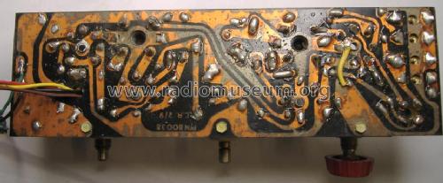
PCB view. Left is DL96 and right is DK96
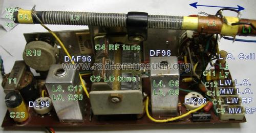
Main components for Alignment.


- Number of Tubes
- 4
- Main principle
- Superheterodyne (common); ZF/IF 470 kHz; 2 AF stage(s)
- Tuned circuits
- 6 AM circuit(s)
- Wave bands
- Broadcast (MW) and Long Wave.
- Power type and voltage
- Dry Batteries / 1.5 & 90 Volt
- Loudspeaker
- Permanent Magnet Dynamic (PDyn) Loudspeaker (moving coil) / Ø 5 inch = 12.7 cm
- Power out
- 0.2 W (unknown quality)
- Material
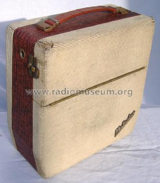
- Leather / canvas / plastic - over other material
- from Radiomuseum.org
- Model: Matador - Berec Radio; London
- Shape
- Portable set > 8 inch (also usable without mains)
- Dimensions (WHD)
- 10 x 4 x 10 inch / 254 x 102 x 254 mm
- Notes
- Attache case radio. Same chassis as Ever Ready model Sky Baronet. Price £13.13s.0d.
Car Aerial socket and Ferrite rod aerial
B141 (combined 90V HT & 1.5V LT) pack with 4 pin socket
Unusually for battery valve portables the tuning has slow motion drive.
- Net weight (2.2 lb = 1 kg)
- 1.8 kg / 3 lb 15.4 oz (3.965 lb)
- Price in first year of sale
- 13.50 GBP
- Source of data
- -- Schematic
- Circuit diagram reference
- Radio and TV Servicing books (R&TVS) book
- Mentioned in
- Attache Radios. By Mark Johnson.
- Author
- Model page created by Keith Staines. See "Data change" for further contributors.
- Other Models
-
Here you find 30 models, 28 with images and 8 with schematics for wireless sets etc. In French: TSF for Télégraphie sans fil.
All listed radios etc. from Berec Radio; London
Collections
The model Matador is part of the collections of the following members.
Forum contributions about this model: Berec Radio; London: Matador
Threads: 2 | Posts: 3
This also applies to the Ever Ready "Sky Baronet". Also the principle is identical for almost every LW/MW Battery Portable. The 1163 sheet may be missing a page on the Sky Baronet Model page.
Signal Injection.
A circular or square loop of about 10 to 20 turns about 10cm diameter is connected to a Signal generator with AM tone (between 400Hz to 1kHz) that should have attenuation in about 6dB to 20dB steps so that on a correctly aligned radio the signal can be barely heard at full volume. A Grid Dip Meter (aka Dip Oscillator) can be used. If in doubt check Dip Meter or signal generator with a frequency counter.
IF Alignment.
It's unusual that it would need done. It's to be avoided as the cores are usually seized and break easily. The capacitors on these kind of IFT are usually very stable and reliable Silver Mica (inside the can). The IF is 470KHZ and the signal can be coupled by putting the generator's loop near the end of ferrite rod that connects to ground or AGC/AVC (depending on Model). Carefully tune for maximum a little at a time on each of the four cores. Each can has two tuned circuits. On some sets the tuning needs to be staggered slightly on each coil if the set is unstable and tuning too sharp/bandwidth too narrow. Best to leave alone unless you know it's been "got at".
RF Alignment.
Don't put the signal generator coil at L2 /L3 end and not too close to the other end. The Generator coil couples at DL96 end outside the case.
It's possible to adjust L3 & L2 spacing and C1, C3, C10 and C12 trimmers without removal from case. IF alignment probably best done after chassis removal, if done at all.
Trimmers from Front panel to rear of case
- C12 LW L.O.
- C10 MW L.O. Affects LW also
- C1 LW RF
- C3 MW RF, Affects LW also
1. Mechanical. Make sure when tuning capacitors are fully closed that the dial needle mechanically matches dial alignment dots (Most dials have these at longest wavelength/ lowest frequency end). It's more common on dial cord models than direct drive or reduction gear.
It's unusual for the local osc coil to need adjustment. It is adjusted at the lowest MW frequency. Best to leave alone (fragile core). Some models are air core and have no adjustment. Adjustment is usally done at 600KHz / 500metres
MW is always adjusted before LW. MW adjustments affect LW, but LW adjustments don't affect MW.
2. MW Highest Frequency Local Oscillator padding: Use Signal generator or a known station near highest frequency end of dial. 214m / 1400kHz is recommended for the "Sky Princess"/Calypso and the Matador seems to have a dash on the dial at that location. Probably 1500KHz/200m would also be reasonable. C10 adjusts the Oscillator. When the dial is matching the Signal Generator you can peak the signal, (keep reducing the Generator level and volume at full) with C2 (RF high frequency padding). Also adjust L2 & L3 spacing, though this has more effect on LW.
3: LW Highest Frequency Local Oscillator padding: Use Signal generator or a known station near highest frequency end of dial. The Matador has a dot at 1100m = 273kHz approx. The Local Oscillator is trimmed by C12 (make sure C11 hasn't snapped off at switch end, it had on mine) and C1 then peaks the RF level. Adjust L2 & L3 spacing on R4 (198kHz, just below 1500m) or French station at 162kHz (about 1850m) and re-adjust C1. Lock L2. (Steel clip, wax or glue)
4: L2 & L3 Interaction. Check C2 on MW at 214m / 1400kHz then C1 on LW at 1100m /273kHz approx. Always re-align LW if you make any MW change.
Notes:
My model was poor on LW and completely deaf on MW. The DF96 was a little low in gain, but the "easily accessible" four trimmer capacitors had obviously been "got at". I used my just recently repaired and restored Taylor All Wave Generator which checked on a modern ferequency counter was found to be accurate and stable enough to align AM Radio sets. I also looked at it on my HP141T Spectrum analyser with 11/110MHz plug in. Previously I would have used my Dip Meter with it's buffered output hooked up to a Frequency Counter. After alignment both MW & LW seemed reasonable for a 1958 Ferrite Rod (the larger Loop aerials are actually more sensitive, such as in Invicta 29 or Ever Ready N or N3).
The Ever Ready "Sky Baronet" is probably identical. These two models appear to be 1958 (very late valve Portables) revision of the 1956 Ever Ready "Sky Princess" (Export version BEREC Calypso). The case is similar but the knobs/dial cover is different. The 1956 version shorts L1 for MW, the 1958 arrangement here is marginally better RF performance. The 1958 version adds C15, R5 (paralleled) in series between L5 and AVC/AGC line. The 1956 version connects the same IFT coil (labelled L4) direct to AVC/AGC line. There may be some changes in component values, but otherwise an identical design and very similar chassis layout. The "Sky Baby"/ BEREC Ballerina is the more conventional (for UK) Valise style case.
I measured HT current at 9.6mA with 60 x AAA Zinc Carbon cells at about 85V. About 110V when new on no load. I was worried initially that this was a little high as my Invicta 29 uses 6.5mA to 7mA. Howver Trader Service Sheet 1305 for "Sky Princess" states total HT is 10.2mA (LT125mA of course). It uses the same 560 Ohms V4 / DL96 grid bias in the HT- feed.
The B141 battery pack may have given over 100 hrs compared with perhaps 30 hours or less on the 1947 Personal B. The Model N3 is similar design though different Chassis layout, so it would have had maybe twice as much or more listening time due to even larger battery packs.
Michael Watterson, 14.Mar.12
The Ever Ready "Sky Princess" / BEREC "Calypso" are very similar to the BEREC Matador / Ever Ready "Sky Baronet" (The BEREC "Ballerina"/ Ever Ready "Sky Baby" are the valise version of "Sky Princess" / "Calypso").
However download the Ever Ready "Sky Baronet" schematic, it's identical.
Most likely needed to be replaced part is C24 (C23 on "Sky "Princess, "Sky Baby" / "Calypso", "Ballerina") a 10nF wax paper betweeen V3 Anode(DAF96) and V4 Grid (DL96).
C21 (Volume control to V3 DAF96 grid) and C15 (IFT 1 to 0V) are same type wax paper 10nF, but less critical as they are in parallel with resistors and have not real voltage across them. They will fail on 100V leakage test, but it likely makes no difference if you leave them.
On my set C11 350pF looked OK, but the end of the wire was not quite touching the switch terminal, resoldering fixed the "missing" Long Wave.
The case was very shabby and all hinges, screws and fittings very corroded, so I stripped it completely. Brasso on the brass, Rustin's "rust remover" (phosphoric acid and meths/ethanol mix) on all the steel parts. Oxi action cleaner, soap and Oxi Action cleaner alternately on all case parts.
I need to find or make a missing knob.
I have scanned the dial plastic and edited out the cracks and dirt. Sometime I will colour print on quality paper and get it colour laser photocopied to OHP film and place that behind a new piece of plastic cut from CD jewel case.
For test I'm using my "Ersatz" 70V B114 pack which with fresh cells is about 75V. I'm making a B141 pack that uses 60 x AAA cells for 90V HT and 1, 2 or 3 x D cells (in parallel) for 1.5V LT. This works out cheaper and longer life than 10 x PP3.
Michael Watterson, 09.Mar.12