504 Ch= 120029 dial 180°
Emerson Radio & Phonograph Corp.; New York, NY
- Country
- United States of America (USA)
- Manufacturer / Brand
- Emerson Radio & Phonograph Corp.; New York, NY
- Year
- 1946
- Category
- Broadcast Receiver - or past WW2 Tuner
- Radiomuseum.org ID
- 109754
-
- alternative name: Emerson Television


RECONSTRUCTED LABEL

RECONSTRUCTED LABEL
Click on the schematic thumbnail to request the schematic as a free document.
- Number of Tubes
- 5
- Main principle
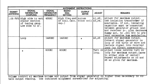
- Superheterodyne (common); ZF/IF 455 kHz; 2 AF stage(s)
- Tuned circuits
- 6 AM circuit(s)
- Wave bands
- Broadcast only (MW).
- Power type and voltage
- AC/DC-set / 105-125 Volt
- Loudspeaker
- Permanent Magnet Dynamic (PDyn) Loudspeaker (moving coil)
- Material
- Wooden case
- from Radiomuseum.org
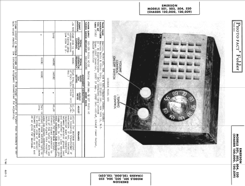
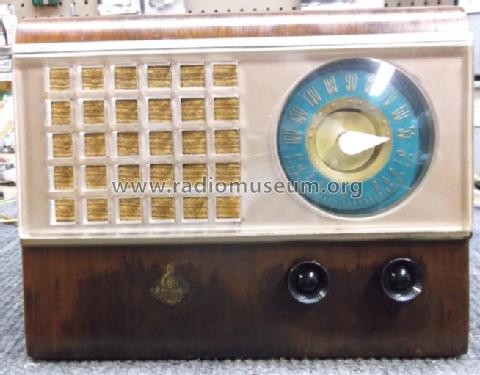
- Model: 504 Ch= 120029 [dial 180°] - Emerson Radio & Phonograph
- Shape
- Tablemodel without push buttons, Mantel/Midget/Compact up to 14
- Notes
- BC Band Tuning Range: 540-1620kHz. Built-in loop antenna. Chassis No.120029 has a 180° dial. Striped walnut or mahogany veneer cabinet, waterfall construction, clear plastic grille.
- Circuit diagram reference
- Rider's Perpetual, Volume 15 = 1947 and before
- Mentioned in
- Collector's Guide to Antique Radios (6th edition)
- Literature/Schematics (1)
- Emerson Radio and Television Service Manual (Page 7)
- Author
- Model page created by Götz Linss † 27.06.21. See "Data change" for further contributors.
- Other Models
-
Here you find 2062 models, 1144 with images and 1618 with schematics for wireless sets etc. In French: TSF for Télégraphie sans fil.
All listed radios etc. from Emerson Radio & Phonograph Corp.; New York, NY
Collections
The model 504 is part of the collections of the following members.
Forum contributions about this model: Emerson Radio &: 504 Ch= 120029
Threads: 1 | Posts: 4
I am recapping an Emerson 504 180-degree dial face tube radio. I am replacing C19 which looks like it reduces mains hum on the output tube. This cap has an isolation coil on it. 0.2 mfd 200 WV Capacitor. Picture Link HERE.
My questions are:
1) How close in mfd does this have to match as 0.2 is not on hand, have 0.25 mfd. 650WV
2) Should this be a safety cap?
3) What should I do with the coil?
4) Do I need to find the outside foil on this one as the use case seems to need more isolation?
Thank you,
Jonathan Reed
Jonathan Reed, 28.Jan.24