- Country
- Great Britain (UK)
- Manufacturer / Brand
- Ever Ready Co. (GB) Ltd.; London
- Year
- 1955
- Category
- Broadcast Receiver - or past WW2 Tuner
- Radiomuseum.org ID
- 135235


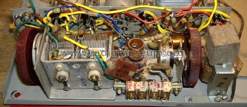
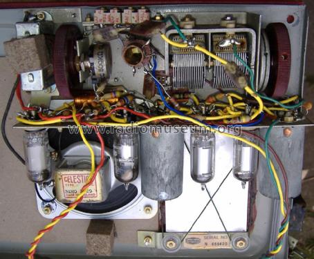
Close up of chassis components after repair.

eBay 150981183659 coolbeanz83
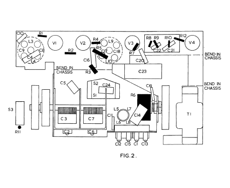
Click on the schematic thumbnail to request the schematic as a free document.
- Number of Tubes
- 4
- Main principle
- Superheterodyne (common); ZF/IF 470 kHz; 2 AF stage(s)
- Tuned circuits
- 6 AM circuit(s)
- Wave bands
- Broadcast (MW) and Long Wave.
- Power type and voltage
- Dry Batteries / 1.5 & 90 Volt
- Loudspeaker
- Permanent Magnet Dynamic (PDyn) Loudspeaker (moving coil) / Ø 10 cm = 3.9 inch
- Power out
- 0.15 W (0.25 W max.)
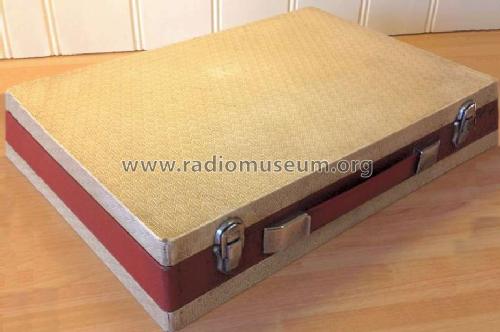
- Material
- Leather / canvas / plastic - over other material
- from Radiomuseum.org
- Model: N3 - Ever Ready Co. GB Ltd.; London
- Shape
- Portable set > 8 inch (also usable without mains)
- Dimensions (WHD)
- 14.252 x 10 x 3.27 inch / 362 x 254 x 83 mm
- Notes
-
Briefcase styled portable radio with large loop aerial in lid.
Uses AD14 (LT) and B107 (HT) battery packs, about 250 hours on AD14 and 150 hours on B107.
Price excluded Purchase Tax.
The Ever Ready N is the earlier version using 50mA valves in 1951 giving then 1/2 life on the AD14.
Specifications (from Ever Ready Service Manual)
- MW 1563 to 560 kHz
- LW 315 to 162 kHz
- On/Off by cabinet lid switch
- Consumption LT 250mA, HT 10.2mA, DL96 Ia 5.4mA
Compared to the "N" the door switch is moved much closer to the rear hinge and drive cord changed from single sided to both sides for greater cursor stability.
Serial number starts with N not N3! This is also seen with C, C/A and C/E where the serial numbers are sequential to the later versions.
The case height (in carry position) is inclusive of hinges, handle and catches. The bare cabinet is 246mm tall. The wieght excludes battery packs which add about 1.5kg. The cabinet depth is slightly more than the original N and also slightly heavier.
The cabinet mix of plywood with hardboard top & bottom panels.The covering is vinyl and cloth Rexine like covering. One "colour way" is grey paint work on the steel panel and another cream with two colours of cloth covering.
- Net weight (2.2 lb = 1 kg)
- 3.2 kg / 7 lb 0.8 oz (7.048 lb)
- Price in first year of sale
- 12.00 GBP
- Source of data
- -- Schematic
- Circuit diagram reference
- Radio and TV Servicing books (R&TVS) book
- Mentioned in
- Attache Radios, Johnson, 2005.
- Literature/Schematics (1)
- Paul Stennings CD, vol 3.
- Author
- Model page created by Keith Staines. See "Data change" for further contributors.
- Other Models
-
Here you find 204 models, 146 with images and 92 with schematics for wireless sets etc. In French: TSF for Télégraphie sans fil.
All listed radios etc. from Ever Ready Co. (GB) Ltd.; London
Collections
The model is part of the collections of the following members.
Forum contributions about this model: Ever Ready Co. GB: N3
Threads: 5 | Posts: 8
Read the BEREC Matador instructions I wrote. The N3 has six rather than 4 adjustments. This allows more accurate alignment of LW and low end of MW.

Prop open the chassis with a block or reel of tape so the 6 trimmer capacitors are just accessible. Make sure there are no metal objects near the lid (loop aerials). Don't work on a Metal workbench!
Put the Generator coil / loop about 4 to 6 cm away behind a corner. Don't place it on or close to lid as that de-tunes the RF.
Trimmer functions
(Note that component designations may not match all schematics)
- C2 : RF high frequency padding (adjust only on MW 1500kHz/200m, affects MW & LW)
- C6 : LO high frequency padding (adjust only on MW 1500kHz/200m,, affects MW & LW)
- C12 LO padding. affects all frequencies. Adjust only on MW 600KHz/500m
- C15 LW only LO padding. Adjust only on LW 176.5KHz / 1700m
- C1 : LW loop HF padding. Adjust only on LW 300KHz for max signal after
- C13 LW LO HF. Adjust only on LW 300kHz / 1000m to tune.
Alignment
a) Mechanical. Make sure extreme low frequency of dial is tuning capacitors fully closed and needle at the unmarked dots just above 1800m & 500m
b) Adjust in the sequence on diagram. Use full volume and as low an RF level as possible.
Step 1 & 3: Adjust C6 for frequency and C2 to peak signal on MW 1500KHz / 200m only.
Step 5: Adjust C13 for frequency and C1 to peak signal on LW 300kHz / 1000m only.
Notes
The large lid and thus large loop aerials make this a sensitive set. It's got very large battery packs to give long listening time.
Michael Watterson, 14.Mar.12
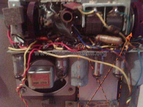
The power switch actually switches the 1.5V and 90V Battery negative connections. The yellow wire is from B107 90V pack and when switch closed (lid open) it's connected to chassis / 0V via 560 Ohms to provide bias for the DL96 grid which is connected to the yellow wire via 2.2 M Ohms.
It wasn't connecting HT- or LT- due to corrosion and wear. The contact at 0V end of 560 Ohms was corroded and also cracked. It was replaced with a small cut-up piece of battery clip from a €2 scrap Auto Scan FM Radio.


The yellow wire only connects to the resistor, no contact. The green wire contacts underneath.
- Yellow = B107 HT- via a tag strip
- Green = Direct to earth tag on Chassis near first IFT
- Black = Direct to AD14 LT- connector
Michael Watterson, 29.Feb.12
I have put 60 x AA cells in the B107 "case"

The battery pack consists of two back to back battery trays:
Bottom (pictured) has 8 columns of 4 x AA cells.
Top has 7 columns of 4 x AA cells
The trays are uncut A4 sheets of card "concertina" folded and then strips of coffee tin slipped into the folds and bent around. The last column at one end has a wire to connector and the other end has coffee tin spring clip to the tray on the other side.
The Battery case design is modified to be a top & bottom "chocolate box" style box with inkjet paper printout stuck on card proir to cutting, folding and joining.
The AD14 pack has two long strips to short 8 x C cells in parallel (do not mix makes or types, don't use rechargeable). I beleive the largest ever pack may have been 6 x F cells in parallel or 8 x D cells in parallel. Not sure which. The AD14 box is also made with lid and base like a "chocolate box".
The sockets are made out of blank PCB drilled and cut to lands with "coffee tin" sockets cut and folded, then soldered to the PCB.
Here is a close up of a B114 pack under construction showing the technique for the socket

Michael Watterson, 29.Feb.12
 The N seems to have been finished in all grey (possibly snakeskin effect) or two tone, grey top and bottom and red band matching inside of lid.
The cloth on the outside of my model had been completely torn off. This small fragment show what the top and bottom was like. (It was under the On/Off switch.
The Red cloth under the rear hinges and front handle matches the loop aerial cover inside the lid.
Ratchford Ltd do have the Red "leathercloth" but the last of the grey with white embossing was sold long ago. They still make a plain grey in "Sand", "Morocco" and "Leather" grain.
Michael Watterson, 28.Feb.12
I have uploaded a cleaned scan of the original paper print in the bottom of the Ever Ready N3 case. Print the two parts at 300DPI to get actual size and trim along join between 90V battery and dotted HT connector postion. It shows the position of the two batteries, but not exactly their size. The Schematic is the Maker's original on the sheet, not a Service book reprint
Michael Watterson, 28.Feb.12