Sky Master Late
Ever Ready Co. (GB) Ltd.; London
- Country
- Great Britain (UK)
- Manufacturer / Brand
- Ever Ready Co. (GB) Ltd.; London
- Year
- 1964 ?
- Category
- Broadcast Receiver - or past WW2 Tuner
- Radiomuseum.org ID
- 174104


eBay item number:314546547513

eBay item number:314546547513
eBay item number:314546547513

eBay item number:314546547513
eBay item number:314546547513

eBay item number:314546547513

eBay item number:314546547513

eBay item number:314546547513
Click on the schematic thumbnail to request the schematic as a free document.
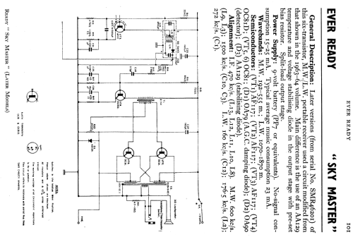
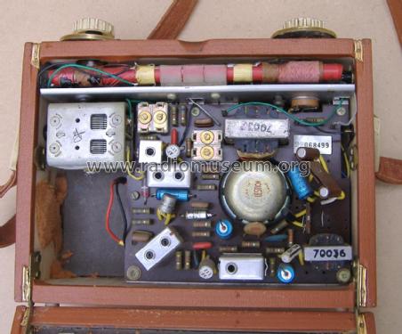
- Number of Transistors
- 6
- Main principle
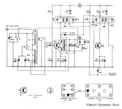
- Superheterodyne (common); ZF/IF 470 kHz; 2 AF stage(s)
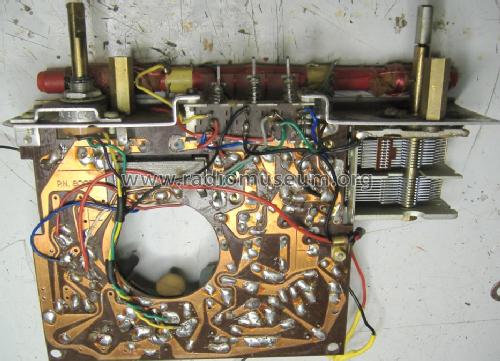
- Tuned circuits
- 7 AM circuit(s)
- Wave bands
- Broadcast (MW) and Long Wave.
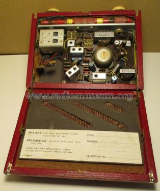
- Power type and voltage
- Dry Batteries / 9 Volt
- Loudspeaker
- Permanent Magnet Dynamic (PDyn) Loudspeaker (moving coil)
- Material
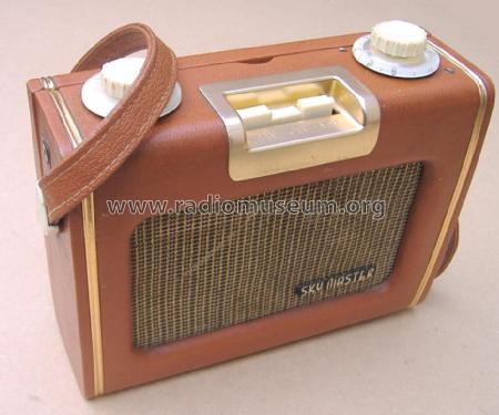
- Leather / canvas / plastic - over other material
- from Radiomuseum.org
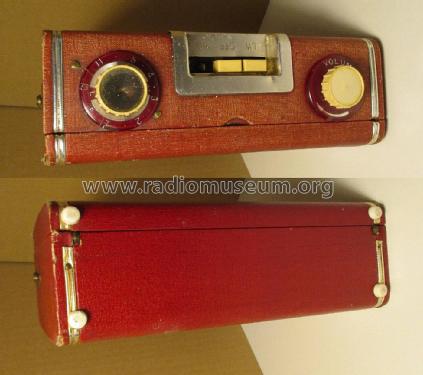
- Model: Sky Master [Late] - Ever Ready Co. GB Ltd.; London
- Shape
- Portable set > 8 inch (also usable without mains)
- Notes
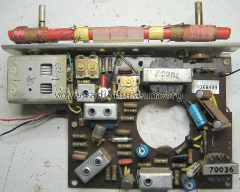
- Later production of Sky Master, serial numbers SMR46201 & upwards have a different temperature stabilising circuit for the audio output stage.
This is a revision of possibly Ever Ready's second transistor set. While the Sky Leader is the first and looks identical, it's actually larger, different internally and uses the PP9 battery rather than the PP7 here.
A PP3 or 6 x AAA in an "ersatz" PP7 box can be substituted.
The radio has both a 3.5mm mono earphone jack socket (disconnecting the internal speaker)and a car aerial socket.
Performance is very good.
The AF117 are well known to fail. They can be replaced with AF127 or possibly Russian NOS Germanium 60MHz types. For the IF and L.O. often PNP Silicon such as BC557 or 2N3906 often work with no circuit modification as replacement for the unreliable AF117.
- Source of data
- -- Schematic
- Circuit diagram reference
- Radio and TV Servicing books (R&TVS) book
- Author
- Model page created by Keith Staines. See "Data change" for further contributors.
- Other Models
-
Here you find 204 models, 146 with images and 92 with schematics for wireless sets etc. In French: TSF for Télégraphie sans fil.
All listed radios etc. from Ever Ready Co. (GB) Ltd.; London
Collections
The model Sky Master is part of the collections of the following members.
Forum contributions about this model: Ever Ready Co. GB: Sky Master
Threads: 1 | Posts: 1
If removing the chassis, note that after gently easing off the inner tuning knob the tuning must be rotated so the flats on the lower and upper parts of shaft are aligned to ease off the dial.
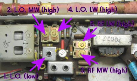
The dial is keyed, so no mechanical alignment of scale.
1) On MW 600kHz (5 on dial = 500m) adjust L.O. coil
2) Adjust trimmer at 1500kHz (2 on dial = 200m) for HF LO tracking
3) Peak RF reception at 1500kHz (2 on dial = 200m)
repeat / recheck 1 to 3
4) On LW adjust trimmer at 272kHz (11 on dial) or RTE half way between 11 and 13 if no generator.
5) Peak RF reception at 272kHz (11 on dial= ) or on RTE 252kHz
Verify that R4 is slightly off 15 on dial (198kHz = 1515m)
Avoid adjusting IF as the cores are fragile, likely to be seized and unlikely to need adjustment unless a radically different transistor is fitted.
Michael Watterson, 06.Jun.12