Capehart 1002-F Ch= P8, changer P71
Farnsworth Television & Radio Corp. - see also Capehart
- Country
- United States of America (USA)
- Manufacturer / Brand
- Farnsworth Television & Radio Corp. - see also Capehart
- Year
- 1950/1951
- Category
- Broadcast Receiver - or past WW2 Tuner
- Radiomuseum.org ID
- 118231


SAMS


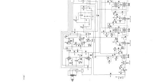
Click on the schematic thumbnail to request the schematic as a free document.
- Number of Tubes
- 11
- Main principle
- Superhet with RF-stage; ZF/IF 455/10700 kHz
- Tuned circuits
- 9 AM circuit(s) 11 FM circuit(s)
- Wave bands
- Broadcast (BC) and FM or UHF.
- Details
- Changer (Record changer)
- Power type and voltage
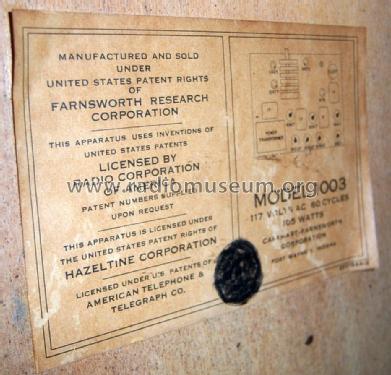
- Alternating Current supply (AC) / 60 Hz, 117V = 110 -120 Volt
- Loudspeaker
- Permanent Magnet Dynamic (PDyn) Loudspeaker (moving coil)
- Material
- Wooden case
- from Radiomuseum.org
- Model: Capehart 1002-F Ch= P8, changer P71 - Farnsworth Television & Radio
- Shape
- Console with any shape - in general
- Notes
-
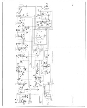
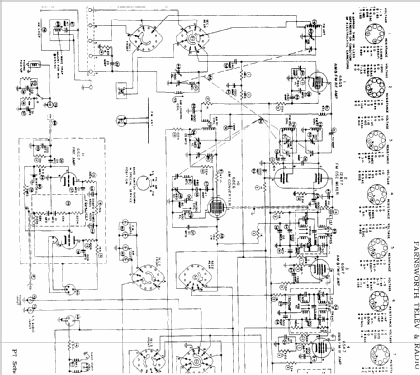
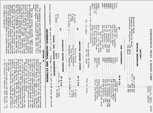
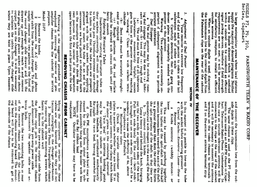
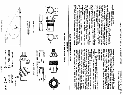
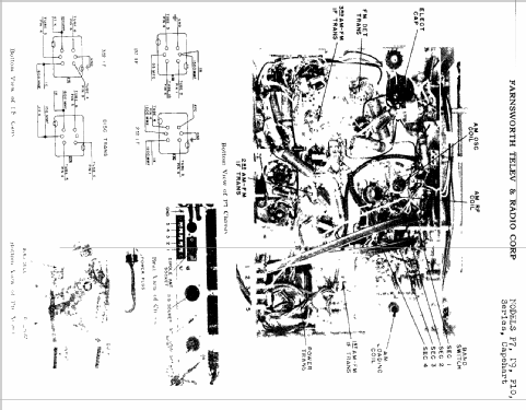
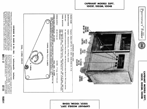
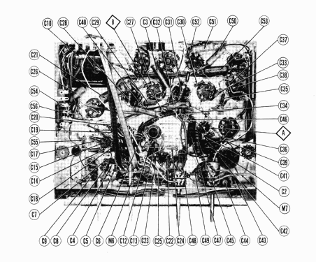
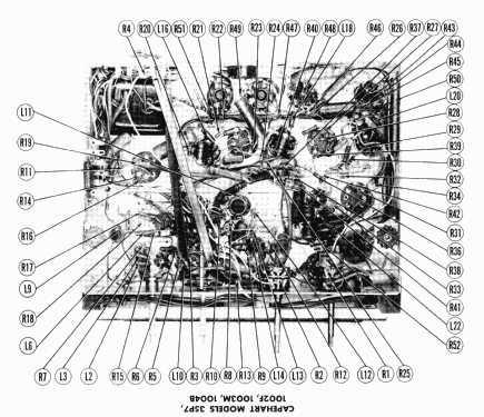
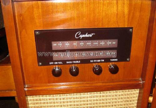
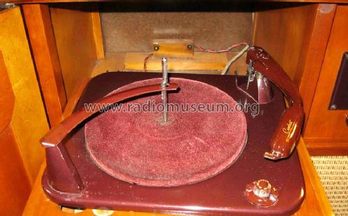
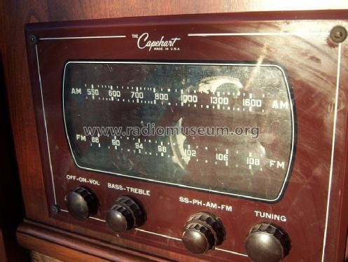
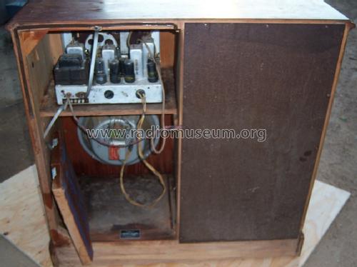
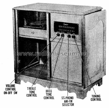
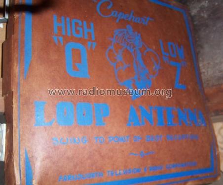
Capehart model 1002F is an AC operated combination phono-radio, AM-FM superheterodyne receiver with loop antenna.
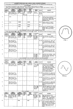
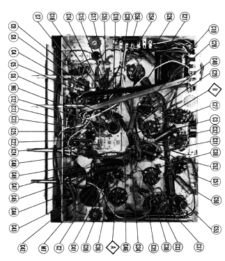
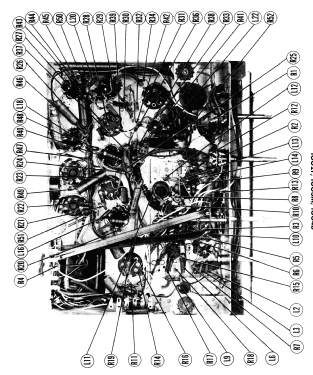
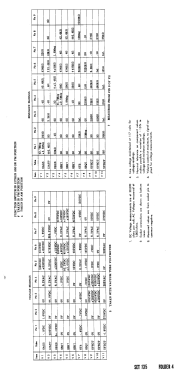
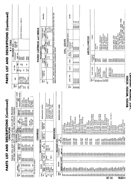
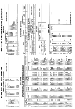
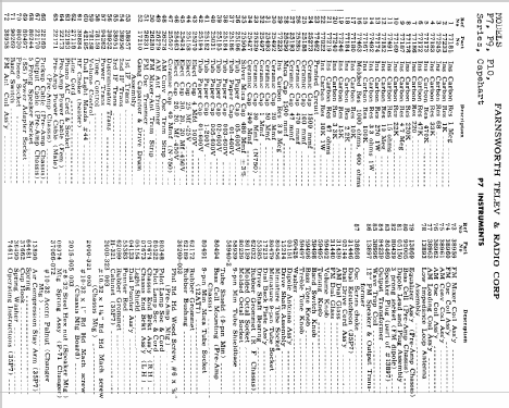
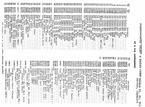
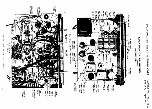
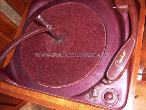
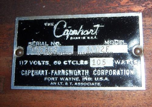
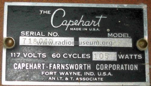
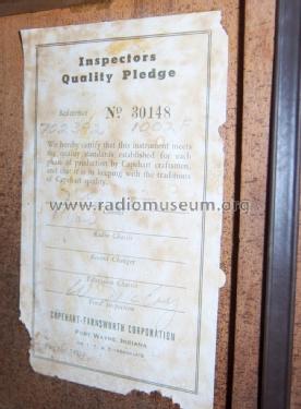
According to SAMS Photofact Date 6-51, set 135, folder 4, the following Capehart models, made by Farnsworth Television and Radio Corp., fort Wayne, Indiana use the following chassis: 35P7 = chassis P-7 (with add. tube 6SC7 for the bias cell and a filament droping resistor), 1002F, 1003M and 1004B = chassis P-8 with a different loop antenna and treble tone control instead of bass tone control. The Record Changer can be a P-71 and there is a built in shielded AM loop antenna for high Q and low Z.Compare the pictures for serial number 702392 with 718040, having a slightly different player and scale (sticker reads also 1003).
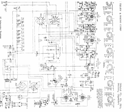
- Circuit diagram reference
- Rider's Perpetual, Volume 21, Copyright 1950
- Literature/Schematics (1)
- Photofact Folder, Howard W. SAMS (Date 6-51, Set 135, Folder 4 + Rider's 19-19 to 19-33)
- Author
- Model page created by Dirk Taekels. See "Data change" for further contributors.
- Other Models
-
Here you find 400 models, 284 with images and 327 with schematics for wireless sets etc. In French: TSF for Télégraphie sans fil.
All listed radios etc. from Farnsworth Television & Radio Corp. - see also Capehart