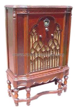
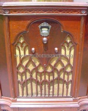
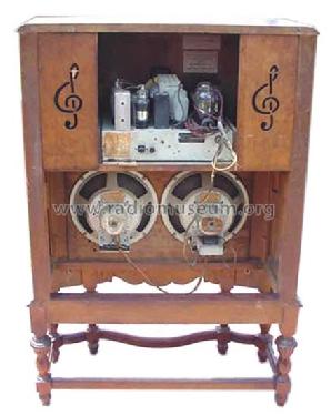
Majestic 310-B Twin Speaker
Grigsby-Grunow (-Hinds) Co. (Majestic pre 1933); Chicago (IL)
- Country
- United States of America (USA)
- Manufacturer / Brand
- Grigsby-Grunow (-Hinds) Co. (Majestic pre 1933); Chicago (IL)
- Year
- 1932 ??
- Category
- Broadcast Receiver - or past WW2 Tuner
- Radiomuseum.org ID
- 43633


Ebay 260638152281

Ebay 260638152281
Ebay 260638152281
Ebay 260638152281
Ebay 260638152281
Click on the schematic thumbnail to request the schematic as a free document.
- Number of Tubes
- 7
- Main principle
- Superhet with RF-stage; ZF/IF 175 kHz
- Tuned circuits
- 6 AM circuit(s)
- Wave bands
- Broadcast only (MW).
- Power type and voltage
- Alternating Current supply (AC) / 110 Volt
- Loudspeaker
- Electro Magnetic Dynamic LS (moving-coil with field excitation coil)
- from Radiomuseum.org
- Model: Majestic 310-B Twin Speaker - Grigsby-Grunow -Hinds Co.
- External source of data
- Ernst Erb
- Circuit diagram reference
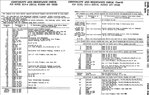
- Rider's Perpetual, Volume 3 = 1933 and before
- Mentioned in
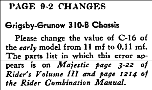
- Rider's Changes 9-2
- Other Models
-
Here you find 201 models, 122 with images and 156 with schematics for wireless sets etc. In French: TSF for Télégraphie sans fil.
All listed radios etc. from Grigsby-Grunow (-Hinds) Co. (Majestic pre 1933); Chicago (IL)
Forum contributions about this model: Grigsby-Grunow -: Majestic 310-B Twin Speaker
Threads: 1 | Posts: 3
The capacitor bypass block is not labeled at least not in any documentation that I can find.
It has 8 capacitors inside and has10 wires and 3 terminals.
I'm hoping someone can help me determine which wire/terminal belongs to which capacitor. I want to replace all of them. I have toyed with idea of taking the block out opening it up to see if each one is labled inside.
I'm attaching photos and a sketch I made showing where the wires/terminal go.
Any help/advice would be greatly appreciated.
Jim
Attachments
- CapByPass_Block (241 KB)
- CapByPass_Block2 (248 KB)
- CapByPass_Block3 (289 KB)
- Majestic310B_Sketch (151 KB)
James Hochstetler, 26.Feb.22