- Country
- United States of America (USA)
- Manufacturer / Brand
- Hastings Products Inc, Boston - Massachusetts
- Year
- 1958
- Category
- Broadcast Receiver - or past WW2 Tuner
- Radiomuseum.org ID
- 151202
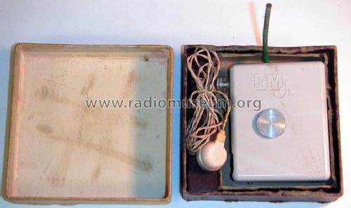

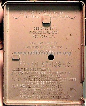
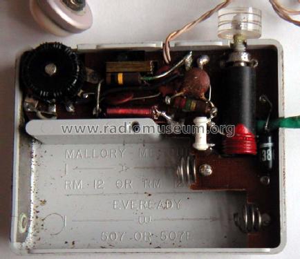
Share Freely. Back side text.
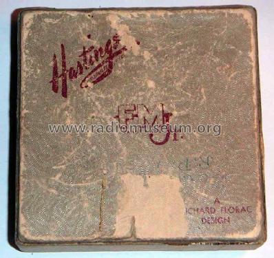
Share Freely. Text inside lid.
- Number of Tubes
- 2
- Main principle
- TRF with regeneration
- Tuned circuits
- 1 FM circuit(s)
- Wave bands
- FM Broadcast Band Only
- Power type and voltage
- Dry Batteries / 1.5; 30 Volt
- Loudspeaker
- - For headphones or amp.
- Material
- Plastics (no bakelite or catalin)
- from Radiomuseum.org
- Model: FM Jr. - Hastings Products Inc, Boston
- Shape
- Very small Portable or Pocket-Set (Handheld) < 8 inch.
- Notes
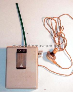
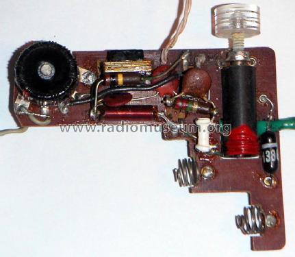
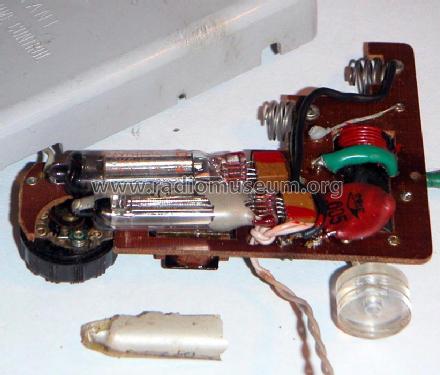
- Shirt-pocket FM(only) Radio, uses subminiature tubes, telescoping antenna.
Although cheap it was a flop. It has no BC band, and in those days FM was for highbrows; classical music through an ear plug was unthinkable. Not until the late sixties there was Rock and Roll on an FM station. The mode of operation is super-regenerative slope detection. Local oscillator oscillates in bursts near incomming frequency at a supersonic burst rate. 1 diode 1N54A reduces local oscillator radiation and improves super-regenerative gain. The diode design was patented by Richard Florac who designed this radio. Relevant US patents by Richard Florac 2619589 2799775 3005910
- Price in first year of sale
- 22.00 $
- Source of data
- -- Collector info (Sammler)
- Mentioned in
- The Portable Radio in American Life (p.195)
- Author
- Model page created by Konrad Birkner † 12.08.2014. See "Data change" for further contributors.
- Other Models
-
Here you find 1 models, 1 with images and 0 with schematics for wireless sets etc. In French: TSF for Télégraphie sans fil.
All listed radios etc. from Hastings Products Inc, Boston - Massachusetts
Forum contributions about this model: Hastings Products: FM Jr.
Threads: 1 | Posts: 2
Forum friends:
After waiting a couple of years with an automatic ebay search, I finally got my Hastings FM-Jr. This FM pocket radio was designed by Richard Florac and made by Hastings Products of Boston Massachusetts, USA in the late 1950's. Florac protected his design with several patents.
The two most relevant patents are US2619589 filed July 29th 1950 and granted November 25th 1952 and US2799775 filed March 1st 1955 and granted July 16th 1957. This later patent was also re-issued as patent US3005910 on October 24th of 1961.
Patent US2619589 shows most of what became the commercial version of the circuit. It is interesting to note that part of the claims include the idea of using an antenna away from the head in a case that was meant to contain the speaker for direct listening against the ear. This could be the first time that the modern form used in cell phones was first protected by a patent.

The second important patent US2799775 covers the most innovative part of the circuit, with the introduction of a point-contact germanium diode 1N54A. The body of the patent can be retrieved from Google-patents and contains a description of values used in the patented circuit.

This patent claims two functions for the 1N54A diode. The first function is implemented in the first schematic, and the purpose is to increase detection gain. The patent claims an improvement of 10dB.
RM member Wolgang Holtman has a very good treatment of FM detection with super-regerarion at this thread:Kosmos X3000, UKW-Pendler mit FET
The amplification in a Super regenerative detector occurs when the RF burst is in exponential growth as shown in the the first scope photo of Kosmos X3000, UKW-Pendler mit FET This section of the curve is labelled "Aufschaukelung".
The "Burst" section of the curve gets detected into a grid-leak or gate-leak bias which ends up extinguishing the burst. The start of the exponential growth is directly affected by the incomming signal. A strong incomming signal will make the exponential growth start more quickly, and a smaller input signal will delay the sart of the exponential growth.
These variations in the time that it takes for the exponential growth vary the average current drawn by the stage at audio rates. The input FM signal does not vary in amplitude until it is tuned by the oscillating circuit, as is the case with slope or flank detection. So the local oscillator should be tuned way from carrier frequency by the maximum FM deviation (+/-75kHz).
The very clever 1N54A diode that Florac added to the FMJr affects the exponential growth portion of the signal, after the exponential growth has enough voltage to turn on the diode. The Burst amplitude is on the orther of a few Volts. When the diode turns on, the exponential growth is slowed, and has greater effect on the the average audio current variations.
But Florac found a second use for his 1N54A diode. He realized that if the diode were placed in series with the antenna, he could still get a slow down in the exponential growth, while isolating the antenna from the burst itself. The antenna sees the envelope detected version of the burst, with much less RF engergy.
The only time that the incomming signal can affect the exponential growth,or regeneration, is at the start of the regeneration cycle, when the incomming signal is similar in magnitude to the growing oscillator signal. Under these conditions, the diode acts as a low loss capacitance, so little sensitivity is lost by adding the diode in the antenna circuit.
Sampled exponential or regenerative growth circuits have been with us since Armstrong first used them for radio detection with super-regeneration. Regeneration is also fundamental to all digital flip-flop circuits. The clock input of a filip-flop is analogous to the quenching action in super regeneration. In most realizations, regeneration is the fastest form of gain that can be achieved. Simply stated, the initial signal of a regenerative cycle grows in amplitude by 2.73x for every time constant that the circuit regenerates. In the example scope photo shown at the thread above, Looking at that scope photo, the regeneration time constant appears to be around 200ns. This means that if the exponential growth portion of the cycle lasts for 10us, the gain would be 2.73^(10u/200n)=5*10^21. This is an astronomic figure, and is conditioned by when the actual start of regeneration occurs. A good part of the cycle after the burst is not regenerative. The gain of 100 that Wolfgang puts on his photo suggest that regeneration occurs for approximatelly 5 time constants of 200ns, or 1us.
There is an apparent discrepancy between this last paragraph and the slowing effect on the exponential growth that the diode causes. Most of the gain from very small antenna signals,could be, perhaps, only 10uV occurs during the faster part of the regeneration cycle that occurs before the diode starts conducting. The later part of the regeneration cycle is slowed by the diode so that this portion has a stronger effect on the duty cycle.
Further comments and understanding of this circuit are invited.
Regards,
-Joe
----------------------------------------------------------------------------------
External links about the Hastings FM-Jr.:
http://www.somerset.net/arm/fm_only_list.html#ConcertNetworks
http://oak.cats.ohiou.edu/~postr/bapix/FloracRd.htm
Joe Sousa, 09.Jun.09