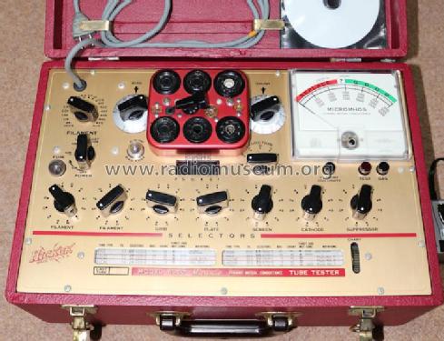
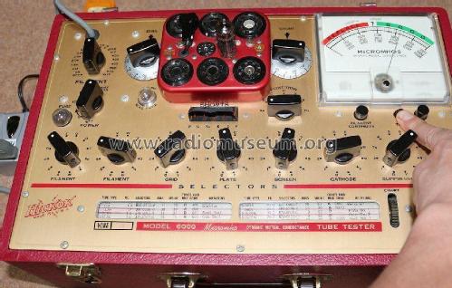
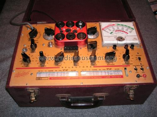
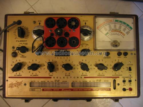
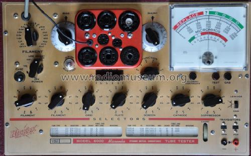
Tube Tester 6000
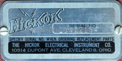
Hickok Electrical Instrument Co.; Cleveland, OH
- Country
- United States of America (USA)
- Manufacturer / Brand
- Hickok Electrical Instrument Co.; Cleveland, OH
- Year
- 1957–1962
- Category
- Service- or Lab Equipment
- Radiomuseum.org ID
- 113444
-
- alternative name: Hickock


aus ebay, #115535058265, Verkäufer dr_nine
aus ebay, #115535058265, Verkäufer dr_nine

aus ebay, Verkäufer riatla

Click on the schematic thumbnail to request the schematic as a free document.
- Number of Tubes
- 2
- Wave bands
- - without
- Power type and voltage
- Alternating Current supply (AC) / 110 Volt
- Loudspeaker
- - - No sound reproduction output.
- Material
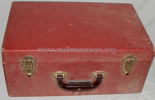
- Wooden case
- from Radiomuseum.org
- Model: Tube Tester 6000 - Hickok Electrical Instrument
- Shape
- Tablemodel, Box - most often with Lid (NOT slant panel).
- Dimensions (WHD)
- 265 x 185 x 425 mm / 10.4 x 7.3 x 16.7 inch
- Notes
- Vereinfachtes Modell des 600; kleiner und leichter gebaut, für Servicezwecke.
- Net weight (2.2 lb = 1 kg)
- 7.3 kg / 16 lb 1.3 oz (16.079 lb)
- Mentioned in
- Alan Douglas, Tube Testers and Classic Electronic Test Gear
- Other Models
-
Here you find 148 models, 132 with images and 42 with schematics for wireless sets etc. In French: TSF for Télégraphie sans fil.
All listed radios etc. from Hickok Electrical Instrument Co.; Cleveland, OH
Collections
The model Tube Tester is part of the collections of the following members.
Forum contributions about this model: Hickok Electrical: Tube Tester 6000
Threads: 1 | Posts: 10
Gentle tube enthusiasts,
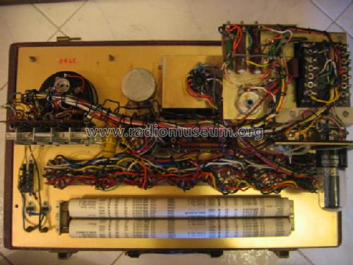
together with fellow Dale Spear, I am working on a project which involves good knowledge of the circuitry and theory of operation of 6000, 6000A and 6005 tube testers.
I have three main concerns:
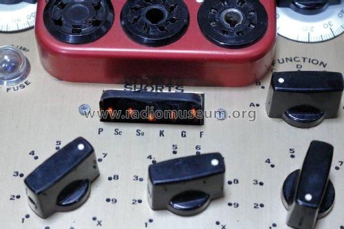
1) the user's manual states that the seven sockets' contact dials have fourteen positions. However, other literature mentions twelve positions. Do they perhaps have two "standby" (= disconnected) positions, which would solve the discrepancy?
2) I particularly seem to have problems with dial 2. It should be marked 1-2-3-R-S-T-U-V-W-X-Y-Z but in the tube charts I consistently find as well a P position. Which socket's contact is connected when it is turned in P position, or which other operation is performed?
3) The "FUNCTION" switch is said to have eight positions. However, the positions used in tube testings seem to be only five: A-B-C-D and F. As long as I understand, A is used for amplifiers' tests, C for diodes' tests and D for rectifiers' tests. But I couldn't find any literature on what B and F functions are used for and what they specifically do. Does anyone have any clue?
Thanks for reading.
Marco Gilardetti, 09.Oct.09