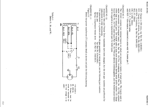
Audio Signal Generator 205AG
Hewlett-Packard, (HP); Palo Alto, CA
- Country
- United States of America (USA)
- Manufacturer / Brand
- Hewlett-Packard, (HP); Palo Alto, CA
- Year
- 1942 ?
- Category
- Service- or Lab Equipment
- Radiomuseum.org ID
- 92179


Fully restored set
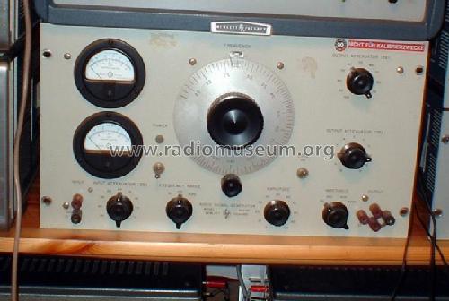
205 AG Rackversion

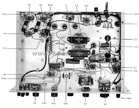
von unten
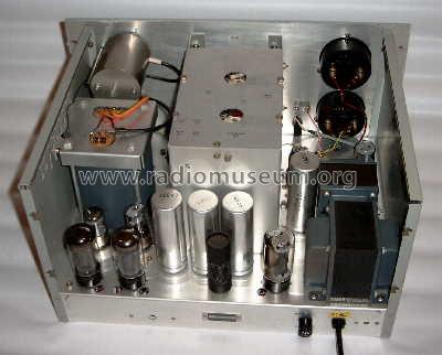
von oben


Audio Engineering April 1949 - Page 2
Click on the schematic thumbnail to request the schematic as a free document.
- Number of Tubes
- 10
- Wave bands
- - without
- Power type and voltage
- Alternating Current supply (AC) / 110-240 Volt
- Loudspeaker
- - For headphones or amp.
- Material
- Metal case
- from Radiomuseum.org
- Model: Audio Signal Generator 205AG - Hewlett-Packard, HP; Palo Alto
- Shape
- Rack
- Dimensions (WHD)
- 19 x 10.5 x 12.75 inch / 483 x 267 x 324 mm
- Notes
-
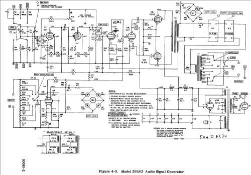
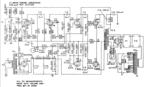
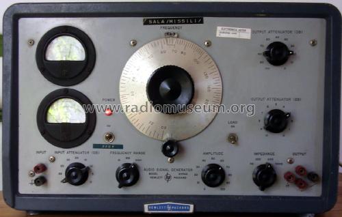
The Model 205 AG Audio Signal Generator contains all the necessary instruments for accurate gain or frequency response measurements. The basic audio oscillator uses a Wein Bridge circuit to generate a sine wave. This sine wave is then amplified and provided at the OUTPUT terminals. Any desired frequency in the range of 20 Hz to 20 kHz is obtainable from the instrument. Two voltmeters are pro vided on the front panel. One voltmeter measures input to the device under test, the second measures output from the device under test. An attenuator is provided to set the
output voltage to the desired level. Output impedance can be changed by means of selector switch to 50, 200, 600, or 5000 ohms.
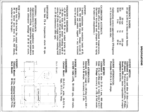
Frequency Range: 20Hz to 20 kHz in three decade bands:
X1 20 Hz to 200 Hz
X10 200 Hz to 2 kHz
X100 2 kHz to 20 kHz
Dial Accuracy: Within 2% of setting at normal ambient temperatures.
Output Flatness:
± 1.5 dB 20 Hz to 20 kHz at output levels > 30 dBm with output meter reading held at +37 dB (reference =1000 Hz). ± 1 dB 20 Hz to 20 kHz at output levels <+30 dBm with output meter reading held at +37 dB.
Distortion:
Less than 1% at frequencies above 30 Hz.
Hum Level:
More than 60 dB below output levels greater than -30 dBm. For output levels of -30 dBm and below hum level will be < -90 dBm.
Output Attenuators:
Provide 110 dB attenuation in 10 and 1 dB steps.
Accuracy:
10 dB Attenuator:
1 kHz ± 0.5 dB, 0 dB to 80 dB ± (5 dB, 90 dB to 100 dB
20 kHz ± 2.5 dB, 0 dB to 100 dB
1 dB Attenuator:
20 kHz ± 0.25 dB, 0 dB to 10 dB
Input Meter:
Calibrated in dBm (0 dBm = 1 mW into 600 ohms) from - 5 to +8 dBm and in volts from 0 to 2 V rms. Voltage accuracy is ± 5% of full scale.
Input Attenuator:
Extends meter range to +48 dBm and to 200 V rms in 5 dB steps. Accuracy is ± 0.1 dB.
Output:
Five watts maximum into resistive loads of 50, 200, 600, and 5000 ohms. Output circuit is balanced and center tapped--any terminal may be grounded.
- Net weight (2.2 lb = 1 kg)
- 24 kg / 52 lb 13.8 oz (52.863 lb)
- Price in first year of sale
- 700.00 $
- Source of data
- -- Original-techn. papers.
- Mentioned in
- ad in Electronics, Jan. and April 1942
- Author
- Model page created by Sven Hoffmann. See "Data change" for further contributors.
- Other Models
-
Here you find 391 models, 359 with images and 138 with schematics for wireless sets etc. In French: TSF for Télégraphie sans fil.
All listed radios etc. from Hewlett-Packard, (HP); Palo Alto, CA
Collections
The model Audio Signal Generator is part of the collections of the following members.
Forum contributions about this model: Hewlett-Packard, HP;: Audio Signal Generator 205AG
Threads: 1 | Posts: 1
The HP 205 Audio Signal Generators
"From HP Catalog 18A" Laboratory
Instruments", Copyrighted 1945."

ADVANTAGES:
No auxiliary equipment needed
Range-20 to 20,000 cps
5 watts output, less than 1% distortion
No zero setting
Supplies known voltage
Output meter calibrated in volts and decibels
Standardized frequencies instantly available
Separate input meter for gain measurements
Wide range of output impedances
USE IT FOR:
Amplifier gain measurements
Network frequency response
Source of voltage for distortion measurements
Broadcast transmitter audio response
Loudspeaker response
General laboratory applications
Production testing
SIX BASIC INSTRUMENTS COMBINED TO SPEED GAIN MEASUREMENTS
All the necessary instruments for accurate gain or frequency response measurements have been assembled by -hp- engineers in one compact unit. (See block diagram.) No auxiliary equipment is required.
This Audio Signal Generator brings new speed and ease to testing jobs. Any desired frequency within the range of 20 to 20,000 cps is made available by the resistance-tuned audio oscillator. These frequencies are developed at any desired voltage between 150 volts and 50 micro-volts.
To make amplifier or network gain measurements with the -hp- Model 205AG Audio Signal Generator, the operator simply connects input and output leads to the binding posts.
Two vacuum tube voltmeters are provided, one to measure input and the second to measure output of the device under test. The input meter has a range of minus 5 db to plus 49 db, with an input impedance of 5,000 ohms. The attenuator sets the output voltage. The output impedance can be instantly changed by means of a selector switch (line matching transformer in the block diagram) to the commonly used impedances of 50, 200, 500, and 5,000 ohms, a convenience in matching various types of networks. The Model 205AG will supply 5 watts output with less than 1% distortion, and thus is useful where sizeable amounts of power are required. Feedback is used for improved frequency response and lower distortion.
The -hp-- Model 205AG is well adapted to measuring frequency response and gain or loss of any network. The frequency remains accurate, without the necessity of zero setting. -hp- Audio Signal Generators are built for heavy duty and long hard service.
AUDIO AND SUPERSONIC MODELS AVAILABLE
There are three models of signal generators. The -hp- Model 205AG provides all of the basic components to make a complete gain measurement in one unit. The -hp- Model 205A is similar to the 205AG except that the input vacuum tube voltmeter is eliminated. For supersonic measurements the-hp- Model 205AH signal generator is available. This instrument is similar to the -hp-- Model 205A but covers a frequency range of 1 kc to 100 kc.
SPECIFICATIONS, MODEL 205AG AND 205A
Frequency Range: The frequency coverage is 20 cps to 20,000 cps, in three ranges.
Calibration: The dial is calibrated directly in cycles for the lowest range, 20 cps to 200 cps. A switch selects the desired range and indicates the proper multiplying factor. Each range covers approximately 270 degrees on the 61/2" main dial. Range 1 covers 20 cps to 200 cps; Range 2 covers 200 cps to 2,000 cps; and Range 3 covers 2,000 cps to 20,000 cps.
Stability: Under normal temperature conditions the frequency will drift less than 2% over long periods of time. Each range is provided with an internal adjustment so that 1% accuracy may be maintained if required.
Output: Five watts output will be delivered to a matched resistance load.
Output Impedances: Output impedances of 50 ohms, 200 ohms, 500 ohms, and 5,000 ohms are available. All are center tapped, balanced and may be grounded if desired.
Frequency Response: The frequency response of the system beyond output meter is down 2.0 db at 20 cps and 1 db at 20,000 cps (at levels from +37 to -30 dbm). Drop in response exceeds these limits at levels lower than -30 dbm.
Distortion: The distortion is less than 1% at rated output at all frequencies above 30 cps.
Hum Level: The hum level is 60 db below the output voltage or 90 db below zero level, whichever is the larger.
Output Meter: The output meter is calibrated directly in volts at 500 ohms and in db above a 1 mw level (50 volts and plus 37 db full scale).
Input Meter: * The input meter has a range of minus 5 db to plus 49 db based on a 1 mw level in 500 ohms. The meter scale is calibrated from minus 5 db to plus 9 db and a multiplier switch adds from zero to 40 db to the reading in 5 db steps. The meter has an input impedance of 5,000 ohms.
* Not included in Model 205A.
Frequency Response: The input meter is compensated to have about 0.5 db rise at 20 kc so that gain measurements with the Model 205AG are accurate to 15 kc and only about 0.5 db in error at 20 kc.
Output A : The output attenuator provides 110 db in 1 db steps. It consists of a 100 db attenuator with 10 db steps and a 10 db attenuator with 1 db steps.
Mounting: Available in either relay rack or cabinet mounting. Panel size on either instrument, 19" x 10 ½". Cabinet models are mounted in oak cabinets. Panels are finished in gray wrinkle enamel with machine engraved designations.
Net Weight: 73 pounds. Shipping Weight: 116 pounds.
MODEL 205AH SUPERSONIC SIGNAL GENERATOR
Frequency Range: 1 kc to 100 kc, in two ranges.
Power Output: 5 watts at 3% distortion, 3 watts at 19c distortion, 1 watt at ½ % distortion.
Output Imped: 50 ohms, 200 ohms, 500 ohms, and 5,000 ohms. All are center tapped (ungrounded) .
Frequency Response: ±1 db from 10 kc reference.
Hum Level: The hum level is at least 65 db below output voltage or 65 db below 1 milliwatt into 500 ohms, whichever is greater.
Output Attenuator: Range: 0 to 110 in 1 db steps.
Accuracy: ½ db in first 80 db, 3 db in last 30 db.
Power Supply: 115 volts, 50-60 cycles, 140 watts.
Accuracy of Frequency: ±2%.
Stability of Frequency: ½ %, after ½ hour warm up. Line voltage changes of 10 % have no effect on frequency as power supply to oscillator is regulated.
Output Meter: The output meter is calibrated directly in volts at 500 ohms and in db above 1 milliwatt level (50 volts and +37 db, full scale).
Mounting: The instrument is available in either relay rack or cabinet mounting. The panel size on either instrument is 19" x 10½". Cabinet models are mounted in oak cabinets.
Net Weight: 63 pounds. Shipping Weight: 110 pounds.
Pius Steiner, 20.Sep.12