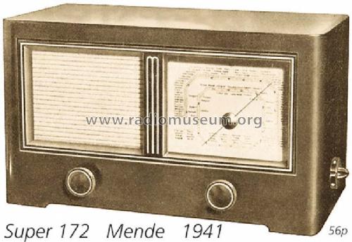
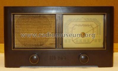
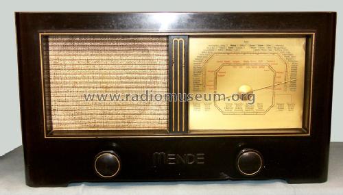
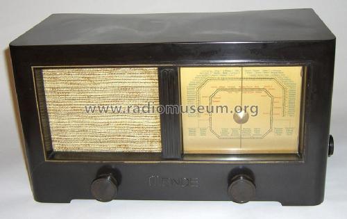
MS172-W (172W)
Mende - Radio H. Mende & Co. GmbH, Dresden
- Country
- Germany
- Manufacturer / Brand
- Mende - Radio H. Mende & Co. GmbH, Dresden
- Year
- 1941–1943
- Category
- Broadcast Receiver - or past WW2 Tuner
- Radiomuseum.org ID
- 3647
-
- Brand: System Günther


ebay 6600551067

ebay 6600551067
ebay 6600551067
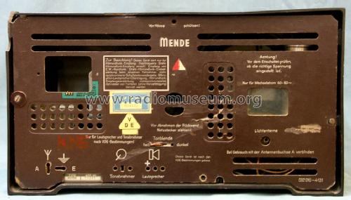


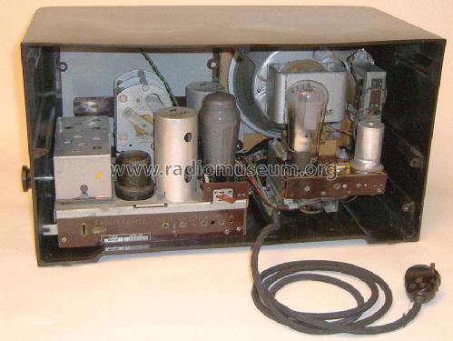
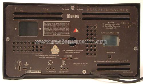

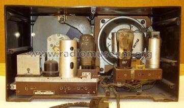
Mende 172W back view
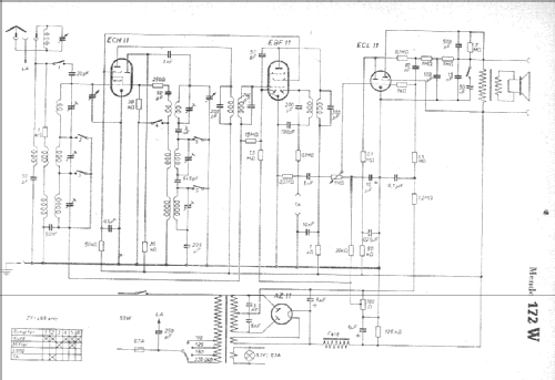
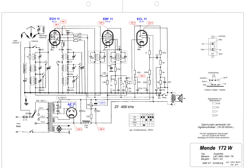
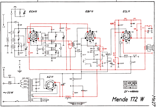
Click on the schematic thumbnail to request the schematic as a free document.
- Number of Tubes
- 4
- Main principle
- Superheterodyne (common); ZF/IF 468 kHz
- Tuned circuits
- 6 AM circuit(s)
- Wave bands
- Broadcast, Long Wave and Short Wave.
- Power type and voltage
- Alternating Current supply (AC) / 110-240 Volt
- Loudspeaker
- Electro Magnetic Dynamic LS (moving-coil with field excitation coil)
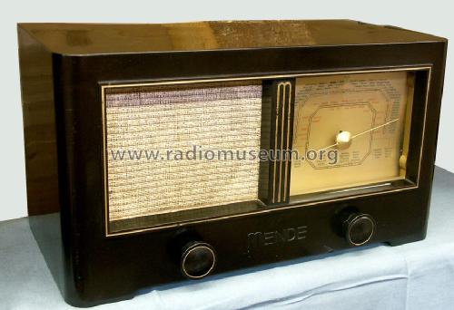
- Material
- Bakelite case
- from Radiomuseum.org
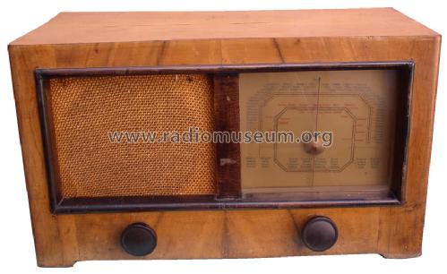
- Model: MS172-W - Mende - Radio H. Mende & Co.
- Shape
- Tablemodel, with any shape - general.
- Dimensions (WHD)
- 420 x 235 x 210 mm / 16.5 x 9.3 x 8.3 inch
- Notes
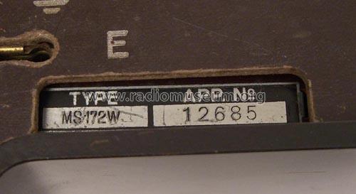
- Das Typschild des Empfängers zeigt MS172-W, dagegen führen die Service-Unterlagen die Typbezeichnung 172W.
Es handelt sich dabei um dasselbe Modell.
- Net weight (2.2 lb = 1 kg)
- 9 kg / 19 lb 13.2 oz (19.824 lb)
- Source of data
- Radiokatalog Band 1, Ernst Erb
- Circuit diagram reference
- Lange+Schenk+FS-Röhrenbestückung
- Mentioned in
- Funkgeschichte der GFGF (9284)
- Picture reference
- Das Modell ist im «Radiokatalog» (Erb) abgebildet.
- Other Models
-
Here you find 314 models, 281 with images and 206 with schematics for wireless sets etc. In French: TSF for Télégraphie sans fil.
All listed radios etc. from Mende - Radio H. Mende & Co. GmbH, Dresden
Collections
The model is part of the collections of the following members.
Forum contributions about this model: Mende - Radio H.: MS172-W
Threads: 2 | Posts: 7
Hallo Sammlerfreunde,
ich möchte mal wieder auf einen Fehler im Schaltplan hinweisen. Die Gegenkopplung von der ECL 11 rechts oben im ersten Schaltplan ist falsch gezeichnet. Das betrifft leider auch den Plan im Empfänger Vade-Mecum S.995 . Die beiden anderen Schaltpläne im RM kann ich nicht beurteilen, da ich sie mir aus bekannten Gründen nicht heruntergeladen habe und die Quelle nicht kenne.
Herzliche Grüße
M. Böhme
Mario Böhme, 04.Dec.14
Greetings!
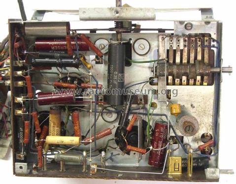
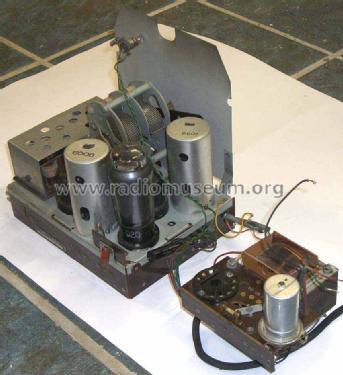
I have one of these Mende 172W radios in which the speaker has been disconnected. I am having trouble understanding the connections to the field coil.
There are 4 connections and four wires going to the field.
In the picture below, I have numbered the connections.
Between 1 and 2, I measure. 3.4 K ohms. Also 3.4 K ohms between points 3 and 4. So it seems that there are 2 windings in the field. There is no connection between the 2 fields.
Between points 5 and 6 measures 600 ohms, so that is the primary of the speaker transformer. No problem there.
Can anyone explain to me why there are these 2 fields and how they should be connected up? The schematic diagram gives a measurement of 1500 Ohms for the field.
Is it that the fields should be connected in parallel?
Sorry, but my German is not quite good enough to explain this problem.
Thanks
Peter
Attachments
- Mende speaker (118 KB)
- Mende speaker 1 (119 KB)
Peter Hughes, 23.May.14