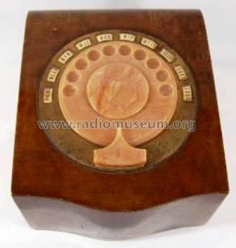
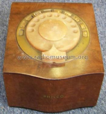
Mystery Control
Philco, Philadelphia Stg. Batt. Co.; USA
- Country
- United States of America (USA)
- Manufacturer / Brand
- Philco, Philadelphia Stg. Batt. Co.; USA
- Year
- 1938–1942

- Category
- Radio module post 1925 (not a part, not a key)
- Radiomuseum.org ID
- 51429


eBay seller shortroundbooks.
aus ebay, Verkäufer kevco12
eBay seller shortroundbooks.

eBay seller shortroundbooks.

aus ebay, Verkäufer kevco12

aus ebay, Verkäufer kevco12


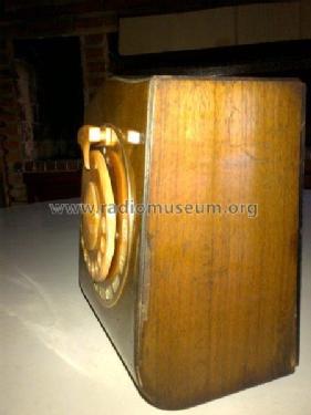
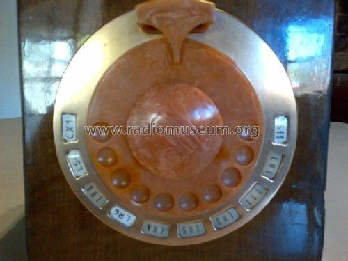
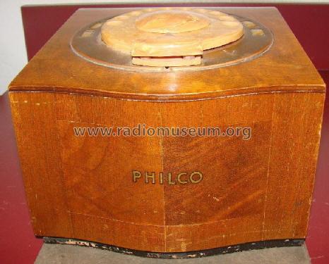
my 1938 philco mystery control

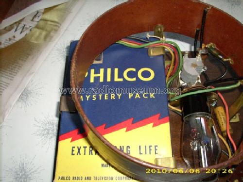
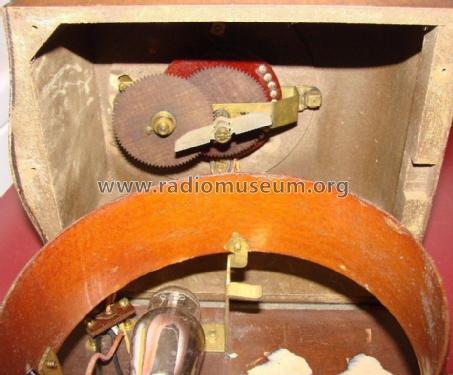
the insides of the mystery control


Click on the schematic thumbnail to request the schematic as a free document.
- Number of Tubes
- 1
- Valves / Tubes
- 30
- Wave bands
- Wave Bands given in the notes.
- Details
- Radio Control (+Remote Wire etc)
- Power type and voltage
- Dry Batteries / 3/45 Volt
- Loudspeaker
- - - No sound reproduction output.
- Material
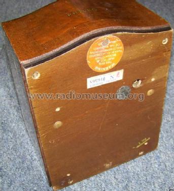
- Wooden case
- from Radiomuseum.org
- Model: Mystery Control - Philco, Philadelphia Stg. Batt
- Shape
- Tablemodel without push buttons, Mantel/Midget/Compact up to 14
- Dimensions (WHD)
- 7.5 x 5.5 x 9 inch / 191 x 140 x 229 mm
- Notes
-
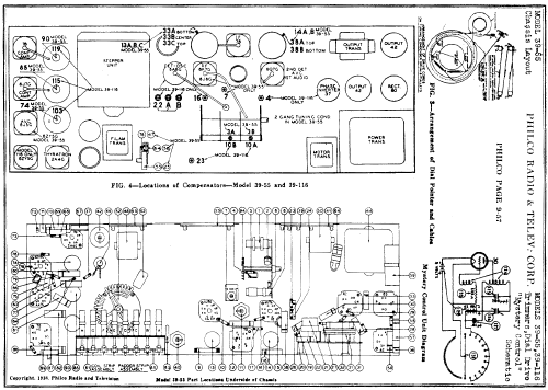
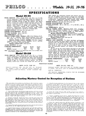
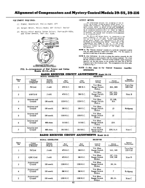
Transmitting on 350-400 kc, this Remote Control for top-of-the-line Philco radios, 1939-1942, like model 39-55 or 39-116. In "Funkschau" 1939, Nr. 17, page 133, a German journal, Mystery Control has been discussed. With writing "Mystery Control" to our SEARCH you will find it.
- External source of data
- Ernst Erb
- Literature/Schematics (1)
- Rider's Perpetual, Volume 9 = 1938 and before (p. Philco 9-61)
- Other Models
-
Here you find 4006 models, 2205 with images and 3656 with schematics for wireless sets etc. In French: TSF for Télégraphie sans fil.
All listed radios etc. from Philco, Philadelphia Stg. Batt. Co.; USA
Collections
The model Mystery Control is part of the collections of the following members.
Forum contributions about this model: Philco, Philadelphia: Mystery Control
Threads: 3 | Posts: 11
The Philco Mystery Control (MC) is of interest because it was the world's first wireless remote control for consumer electronics. While there is some information available today about the electrical operation of the MC, the precise details of its mechanical operation appear to be lost. Philco considered this device to be a "no user serviceable parts" type of unit and any problems were referred back to the factory. As far as I know, there is no documentation on precisely how the MC operates. This is important, because it is difficult to tell if operating problems one may encounter with one of the Philco MC models are due to the MC transmitter or the receiver in the radio.
EXPERIMENT 1 - Controlling the MC receiver
To help resolve this, I devised the following experiment. Using a Basic Stamp microprocessor, I connected a relay to the MC transmitter to act as an emulator for the MC's mechanical pulsing unit (fig. 1).
 Figure 1 - Experimental Setup
The relay used is a Radio Shack 272-232 SPST relay with a 20 ma. 5 V. coil that can be driven directly from an output pin on the Basic Stamp. The relay is visible at the bottom of the board in figure 2. (The other devices on the board are unrelated to this experiment). One relay terminal is connected to the black wire of the MC plug, and when the experiment begins the other relay terminal is connected to both the red and MC yellow wires. Connecting red and yellow together normally happens when the MC dial is "wound up" (rotated CCW) during operation. This activates the no. 30 tube heater in the transmitter but does not send any pulses yet. (Red and yellow remain connected as long as the dial is in motion. Pulses are sent during the dial's return rotation). A complete emulation would require a second relay to perform this, but for our purposes a simple clip lead is sufficient. (Just remember to unclip red from yellow when done).

Figure 2: the Basic Stamp
Next, I wrote a small program that emulates the pulses that should be generated by the mechanical dial to control the receiver. This program is given in listing 1 at the end. The MC transmitter is now entirely under microprocessor control. The mechnical pulser is out of the loop.
PROCEDURE
The MC performs two main functions:
1. Volume control
2. Station selecting
How this is done is covered in my RM article under the Philco 39-116 model. Here I wanted to determine the optimal pulse length and pulse width to reliably activate the relays in the receiver and assure accurate station selection without skipping or hanging. The program contains a variable, Flash, which controls the pulse width. The pulse gap is simply set as a constant in the main loop. All values are in milliseconds. By varying both the pulse width and pulse gap, I was able to determine the optimum values for controlling the receiver. For each value of each variable tested, I activated the receiver three times on stations 1, 4, and 8. If the receiver did not respond correctly (switching to the desired station) all three times, then that marked the limit of that variable.
The program also emulates the MC's volume control pulses. Holding down the fingerstop is emulated by the PAUSE 2000 statement. This equates to a 2 second volume change. When running the volume down, one must be careful not to go too long or the radio will shut off when the volume control reaches the end of its travel. (That's a feature not a bug).
RESULTS
Using the Basic Stamp, I was able to empirically determine that the MC receiver will respond to pulses of length between 30 and 50 msec., with the optimal pulse width in the center of the range, or 40 msec.
The interpulse gap has more leeway. The receiver will work with a gap between pulses of 40 to 100 msec., with 70 msec. being optimal.
If either of these values is outside the above ranges, the receiver operation will be erratic. It may select the wrong station, activate the wrong volume function, or fail to respond at all. There is a 5-10 msec. "gray zone" at each end, where the receiver responds, but incorrectly. Beyond that, the receiver will not activate at all. One can imagine that the Philco engineers designed in some fairly strict limits as a means to avoid interference from stray RF pulses.
EXPERIMENT 2 - Reading the MC Pulser
These results were encouraging, as they confirmed to me that my receiver was operating correctly. This meant that my problems were due to the operation of my MC. To test this, I wrote a second program (see Listing 2 below) that captures the pulses generated by the MC pulser unit. The Basic Stamp setup is very simple: Vdd from the board is connected to the black wire of the MC pulser. The red (or yellow, it doesn't matter) is connected to any Stamp I/O pin via a 220 ohm current limiting resistor and a 10K pulldown resistor. When the MC generates pulses, the switching action causes the Stamp pin to change its logic state. The program reads and outputs this.
This program returns a string of 1's and 0's that I simply copied into Matlab to produce the graph in figure 3 (see Listing 3). With this I was able to test the operation of the pulser and graphically see what it was doing. For example, this is what my MC does when selecting station 8:

Figure 3: Mystery Control selecting station no. 8
From this it is clear that my MC is running too slowly and had one bounced pulse (no.9). In addition, the pulses are not of consistent length, which is also a problem. However, using this diagnostic tool helps me accurately see the effects of various repairs such as oiling or mechanical adjustments to the mechanism to bring the unit back into spec.
CONCLUSION
The use of microprocessors and computers provides a simple and effective means of troubleshooting problems that would otherwise be difficult to solve. This demonstration also provides the basis for a full MC emulator. By connecting the relay to a small modern low-power UHF AM transmitter, one could replace the entire Mystery Control box. This could be useful to people who own an MC-enabled receiver but do not have the MC unit itself. Since the Basic Stamp is easily networked, if could also be remotely controlled from a PC or PDA.
LISTING 1 - Mystery Control Emulator
' MysteryController.bsp
' Philco Mystery Control Emulator
' This program generates pulses to control a Philco Mystery Control transmiatter.
' Uses a Radio Shack 272-232 SPST relay with 5 v. 20 ma. coil
' driven directly from Basic Stamp pin 11.
' Connect one relay terminal to the black wire of the MC.
' Connect the other terminal to the red and yellow wires of the MC.
' Reliable activation range = 30 - 50 msec. pulse width (40 optimal) and
' 40 - 100 msec. pulse spacing (70 optimal)
' Loop execution overhead is negligible, assuming 41 - 83 usec. / instruction
' for the BS2P
' {$STAMP BS2p}
' {$PBASIC 2.5}
#SELECT $STAMP
#CASE BS2, BS2E, BS2PE
Scale CON 500 ' to ms for 2 us per unit
#CASE BS2SX, BS2P, BS2PX
Scale CON 1250 ' to ms for 0.8 us per unit
#ENDSELECT
Flash CON 40 * Scale ' pulse length in milliseconds
n VAR Nib ' loop counter
station VAR Byte ' the station number to tune in, 1 to 8
mode VAR Nib ' station select or volume control
mode = 2 ' 0 = station sel., 1 = vol. up, 2 = vol. dn.
IF mode > 0 THEN ' volume control mode
FOR n = 1 TO mode
PULSOUT 11, Flash ' pulse relay
PAUSE 70 ' delay (pulse interval) in msec.
NEXT
HIGH 11
PAUSE 2000 ' hold down the fingerstop to run the motor
LOW 11
ELSE ' station select mode
LOW 11 ' make P11 low (off state)
station = 7 ' select a station
FOR n = 1 TO station + 3 ' Dial it!
PULSOUT 11, Flash ' pulse the relay
PAUSE 70 ' delay (pulse interval) in msec.
NEXT
ENDIF
END
LISTING 2 - Mystery Control Pulse Reader
' {$STAMP BS2p}
' {$PBASIC 2.5}
' Read the pulses generated by the Philco Mystery Control pulser unit.
' Cicuit: Vdd -> MC red (or ylw)
' MC black -> 220 ohm res. -> pin 11
' Vss -> 10K res. -> MC black
mcin VAR Word
n VAR Word
DEBUG "Start"
FOR n = 1 TO 400 ' 400 samples * 10 ms. = 4000 ms. = 4 seconds of data
mcin = IN11
IF mcin = 1 THEN
DEBUG "1"
ELSE
DEBUG "0"
ENDIF
PAUSE 10 ' msec.
NEXT
DEBUG "Done"
LISTING 3 - Matlab graphing code
function plotpulse (p)
clf ;
np = zeros (1, length (p)) ;
for i = 1:length (p) % Convert string to numeric
if p(i) == '1'
np(i) = 1 ;
end
plot (np) ;
set (gca, 'YLim', [0 2]) ;
set (gca, 'YTick', []) ;
set (get(gca,'XLabel'),'String','msec. * 10') ;
end
Michele Denber, 25.Jul.09
Hello, dear Radio Collectors. Hopefully, someone else with an aptly named Mystery Control can answer this question: how fast should the dial turn? If I select the last station hole and crank the dial all the way around to the stop and let go, it takes my unit approximately 3.5 seconds to return to the rest position. Since the unit sends pulses that activate a stepper relay in a receiver in the radio, I assume that the pulse speed is important. Does this sound like the correct rotation speed?
Update, 4/16/09:
No one answered my post here so I tried antiqueradios.com There I learned that the dial speed should probably be a second or so faster. I won't really know until I get both the Mystery Control and the radio running, In the meantime,I will mark this post as no longer needing an answer.
Michele Denber, 11.Apr.09
Hello, Dear Radio Collectors. I just got one of these fascinating devices and have a few questions. First, my unit came with a 67.5 v. B battery in it. However, the model page shows it uses a 45 V. battery. Which is correct?
Second, the dial is slghtly warped in one spot. It seems to be made of some sort of plastic. Does anyone have any recommendations on how to flatten it out? Is that even possible without damaging it?
Third, does anyone have a picture that shows how the batteries were placed inside the unit? Apparently, there was a separate plug for the batteries which is missing from mine. Someone just soldered two D cells together for the A battery and then poked the wires into the 4 pin plug.
Fourth, while I'm waiting for a radio that matches this remote control, does anyone have an idea of how to test it to see if it works?
I'm also looking for a schmatic for it.
Thanks!
Michele Denber, 25.Mar.09