Radiola 26 (reflex)
RCA (RCA Victor Co. Inc.); New York (NY)
- Country
- United States of America (USA)
- Manufacturer / Brand
- RCA (RCA Victor Co. Inc.); New York (NY)
- Year
- 1925/1926

- Category
- Broadcast Receiver - or past WW2 Tuner
- Radiomuseum.org ID
- 54644
-
- alternative name: RCA Manufacturing || Victor Talking Machine


Ebay Nr. 300070667825 Bild bearbeitet.

Inside catacomb in parafin

Ebay Nr. 300070667825 Bild bearbeitet.


Ebay Nr. 300070667825 Bild bearbeitet.


Ebay Nr. 300070667825 Bild bearbeitet.

Ebay Nr. 300070667825 Bild bearbeitet.


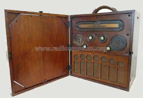
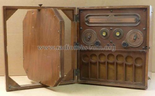
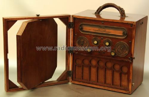
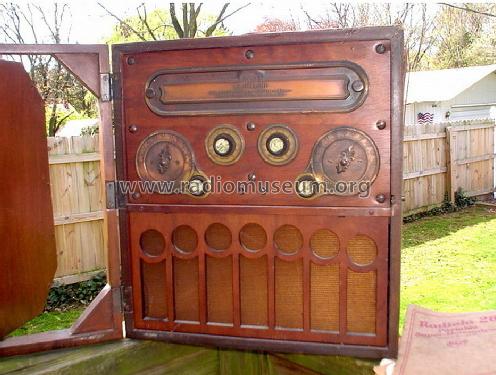
Antenna inside the door


Ebay User zekeyman50 Item 251033872067

Ebay User zekeyman50 Item 251033872067

Ebay User zekeyman50 Item 251033872067


Click on the schematic thumbnail to request the schematic as a free document.
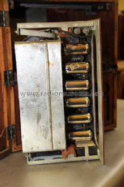
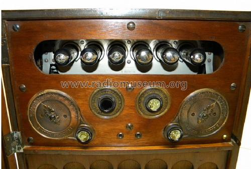
- Number of Tubes
- 6
- Main principle
- Superhet with RF-stage; 2 AF stage(s); Reflex
- Tuned circuits
- 5 AM circuit(s)
- Wave bands
- Broadcast only (MW).
- Power type and voltage
- Dry Batteries / 2 x 45 & 6 x 1.5 Volt
- Loudspeaker
- Horn
- Material
- Wooden case
- from Radiomuseum.org
- Model: Radiola 26 - RCA RCA Victor Co. Inc.; New
- Shape
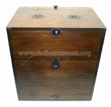
- Portable set > 8 inch (also usable without mains)
- Dimensions (WHD)
- 330 x 360 x 235 mm / 13 x 14.2 x 9.3 inch
- Notes
-
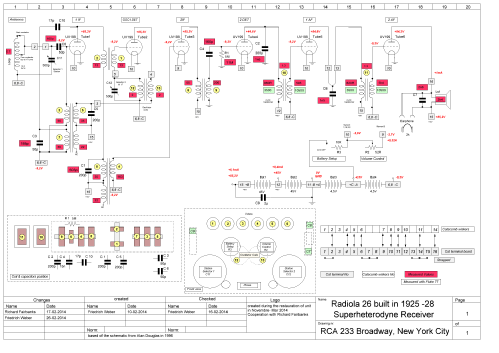
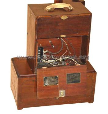
The model RCA Radiola 26 is a repacked AR-812 without the possibility to switch between 5 tubes or 6. It is a real portable with a self contained loop aerial, loudspeaker and batteries. Quite compact for that time - and powerful with its reflexed first tube, achieving 5 circuits.
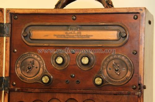
2nd harmonic mixer; two dials (primary tuning control knobs) .Self contained loop aerial.
V1 = RF & 1st IF reflexed.
V2= Oscillator/1st Detector.
V3= IF.
V4= 2nd Detector.
V5= 1st AF.
V6= 2nd AF..
- Net weight (2.2 lb = 1 kg)
- 11.2 kg / 24 lb 10.7 oz (24.67 lb)
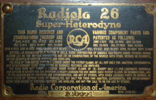
- Price in first year of sale
- 225.00 $
- External source of data
- Ernst Erb
- Source of data
- The Radio Collector's Directory and Price Guide 1921 - 1965
- Circuit diagram reference
- Rider's Perpetual, Volume 1 = 1931/1934 (for 1919-1931)
- Mentioned in
- Collector's Guide to Antique Radios 4. Edition
- Literature/Schematics (1)
- Radio Manufacturers of the 1920's, Vol. 3
- Other Models
-
Here you find 5118 models, 3224 with images and 4151 with schematics for wireless sets etc. In French: TSF for Télégraphie sans fil.
All listed radios etc. from RCA (RCA Victor Co. Inc.); New York (NY)
Collections
The model Radiola is part of the collections of the following members.
Museums
The model Radiola can be seen in the following museums.
Forum contributions about this model: RCA RCA Victor Co.: Radiola 26
Threads: 3 | Posts: 7
Friedrich Weber of Germany had aquired a Radiola 26 in an internet auction and restored it in commendable cooperation with our member Richard Fairbanks, USA.
Although pretty distant from each other the internet enabled quick and efficient exchange of correspondence in word and image. Let him tell his story:
-------------------- -------------------- -------------------- -------------------- -------------------- --------------------
After a three weeks travel across the pond and 19% import duty the radio was unpacked.
Being rather unexperienced in this old technology I searched for information and found
Richards report. I contacted him asking for help. He assisted willingly.
Checking the overall condition of my aquisition it looked not too bad

I found a homebrew power supply in the battery compartment.

No information attached, so I refrained from a test or use. Later I made my own power sources for all the different voltages.

All six tubes were placed in their sockets, cushioned by wrapped newsprint. No damage, thank goodness!
Red powder distributed seemed to be the remains of deteriorated absorption material against effects (e.g. howling caused by acoustic feedback from the speaker).

The catacomb and the terminal strip were bent. Probably caused by a hard drop sometimes in the past.
The potting compound was already removed. But the wires to the catacomb were brisk, breaking apart after slight bending. Inside wiring displayed extremely thin wires.
To replace the wiring the terminal numbering was a puzzle first. Based on a schematic diagram from Alan Douglas a new diagram was drawn with all information related to my set. Richard did the final drawing check.
Both audios had open primaries, a defect not uncommon with such old stuff. Anyway they were not original parts. Somebody had them already replaced. The originals used formerless windings. For the new ones I had to use cardboard coil formers. AWG 42 = metric 0.063 Cu; primary 3500 turns (820 Ohms) and secondary 10500 turns (10500 Ohms) give a ratio of 1:3.


The loop antenna lacked continuity: a defect door contact was the culprit. Repair with copper braid for the hinges provides a safer contact than the original litz wires did.
The horn speaker is fixed on three elements. All three were brittle and broken. A new rubber element plus some transparent silicon rubber did the job.
The big 2µF cap was leaking and had to be "refilled" with a modern component which is well hidden.
Before firing up the set a continuity test is advisable, without tubes, battery cables disconnected (there are relevant tables in the schematics/technical documentation).
After successful test, tubes replaced und power connected the Radiola 26 plays like new.

I am happy! Thank you, Richard!
-------------------- -------------------- -------------------- -------------------- -------------------- --------------------
Editors remarks:
This is a comprehensive issue of Friedrich Webers results. Congratulations!
I would like to add that this early Superheterodyne family employs two special features to be noted:
1) the first tube is reflexed. It amplifies RF and IF simultaneously.
2) for transposition the 2nd harmonic of the oscillator freqency is applied. Consequently the oscillator frequency is far below the signal frequency where the loop antenna is tuned. This prevents radiation of oscillator through the aerial.
Konrad Birkner † 12.08.2014, 01.Apr.14
Hallo Radiofreunde,
kennt jemand die Werte der Kondensatoren, die im Radiola 26 verbaut sind? Der Empfangsteil Rö1-Rö3 funktioniert nicht und ich bräuchte einen Anhaltspunkt was ist Richtig. Als Zwischenfrequenz wird ca. 42kHz angenommen. Der Oszillator schwingt nicht. Eine Unterbrechung wurde bisher nicht gefunden. Röhren sind gut. Anoden- (+70-90V) und Gittervorspannung (-7-9V) sind im Bereich. Hat jemand eine Strategie, wie man hier vorgehen könnte, den Fehler zu finden.
Achtung! der richtige Plan für den Radiola 26 sind Sch1a und Sch1b aus dem RMorg.
Vieen Dank für eine Information.
Friedrich Weber † 12.09.2014, 27.Jan.14
Hello friends,
my next object to restore is a Radiola 26. In the schematic there are 2 open end called DEAD END
 shown. For what is that? Does somebody know the background behind this? Thank you for help.
Best regards
Friedrich Weber
Friedrich Weber † 12.09.2014, 07.Nov.13