Reinartz Moduloscope Homebrew (Tesla) Moduloskop Modulascope
Reinartz, John L. Co.
- Country
- United States of America (USA)
- Manufacturer / Brand
- Reinartz, John L. Co.
- Year
- 1923–1932

- Category
- Miscellaneous (Other, Various) - see notes
- Radiomuseum.org ID
- 275532


Scan by americanradiohistory.com.

Scan by americanradiohistory.com.

Scan by americanradiohistory.com.


Click on the schematic thumbnail to request the schematic as a free document.
- Number of Tubes
- 1
- Valves / Tubes
- Main principle
- Transmitter; something special ? Please give information (notes)
- Wave bands
- Wave Bands given in the notes.
- from Radiomuseum.org
- Model: Reinartz Moduloscope Homebrew Moduloskop Modulascope - Reinartz, John L. Co.
- Shape
- Tablemodel, with any shape - general.
- Notes
-
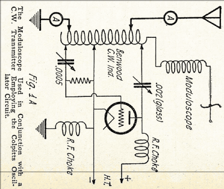
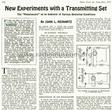
In the 1920's John L. Reinartz was writing many articles about radio technique, not only in "Radio News". With title "New Experiments with a Transmitting Set" he reminded the readers about his invetion of the Moduloscope, described the principles and explained how to build his "electric Windmill" as "an Indicator of Various Operating conditions".
You find here his text as scans from the "Radio News" September 1927, page 238/239. Hopefully we will be able to also publish some photos of builds like late Alan Douglas did an example of in 1977. Alan was a great person, helping others all the time - who wrote excellent books on the radio manufacturing history of the USA for the 1920's.
- External source of data
- Ernst Erb
- Mentioned in
- Radio News (1927, September, page 238-239 by John L. Reinartz)
- Literature/Schematics (1)
- QST (June 1923, page 9.)
- Author
- Model page created by Ernst Erb. See "Data change" for further contributors.
- Other Models
-
Here you find 2 models, 2 with images and 1 with schematics for wireless sets etc. In French: TSF for Télégraphie sans fil.
All listed radios etc. from Reinartz, John L. Co.
Forum contributions about this model: Reinartz, John L. Co: Reinartz Moduloscope Homebrew Moduloskop Modulascope
Threads: 1 | Posts: 11
It is a fact that we should attract young persons to our hobby fro having followers who are interested also in our collection when we pass away. It is a fact that at least in Europe young persons are not interested in radios because they get them in superb quality for nearly no money and AM stations are missing for building simple radios and detectors.
And it is a fact that interest as such is part of a character but may be perhaps teased with spectacular experiments with radio waves. "Interest as such" is the opener for a good and happy career since one does not a job but a vocation!
This all is the reason why I switched from samall radio projects for young people to other techniques for demonstration of interesting characteristics of electricity and radio waves, such as high voltage (Wimshurst or Bonetti or others), Geissler or Crook tube experiments, gentle electrifying sets, sets for tickeling persons (HF-nervstimulator, "med. Reizstromgerät"), very early radio waves or HF-buzzer, Tesla experiments, early transmitter / receptor, mysterious music (theremin), etc. For the latter we know more complicated gear - the too complicated Trautonium.
Even the unipolar machine of Barlow (Barlow's wheel or a homopolar or unipolar generator) can be of interest. Later some radio experiments and views with a simple oscilloscope or with just a tube for it may be possible.
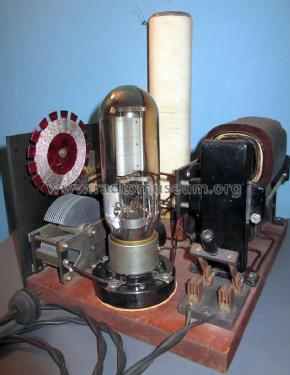
Very near to radio and simple to build - with radio parts - is the homebrew Reinartz Moduloscope. Sometimes it is also called vacuum tube Tesla coil. Philip Colston, Setauket, USA, was so kind to send me an OCR scan from "Modern Mechanics" of 1932 of the article how to build an other version. I can just use his scan and will add some pictures from the journal.
Vacuum Tube Tesla Coil Does Fascinating Stunts
from Modern Mechanics & Inventions, January 1932, page 92 - 94 and 140/141.
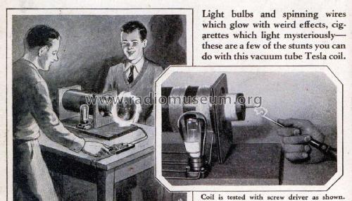
Light bulbs and spinning wires which glow with weird effects, cigarettes which light mysteriously—these are a few of the stunts you can do with this vacuum tube Tesla coil.

You find all five pictures large (1400 pixels width) on the model page.
See also other builds there.
THE older types of Tesla coils, calling for a high tension transformer and spark gap for excitation, were undoubtedly interesting and instructive, but the one shown in the accompanying photographs and sketches will prove much less expensive to construct and yet will provide plenty of sure fire fun and spectacular results. It makes use of many radio parts and therefore should prove very inexpensive to construct by those readers possessing a stock of spare radio “junk.” It is simply a matter of plugging in to the 110-volt electric light line to carry on an almost endless number of interesting and instructive experiments in high frequency currents.
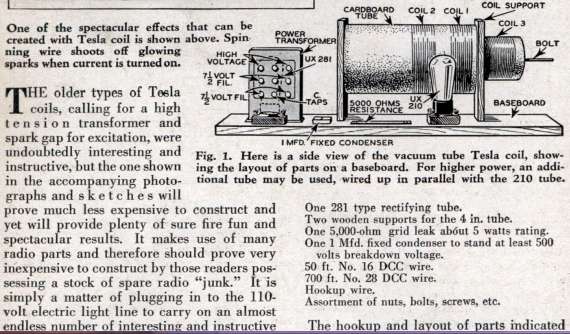
You will need the following parts:
A baseboard 18 in. long by 10 in. wide.
Cardboard tube 8 in. long, 4 in. diameter.
Cardboard tube 11 in. long, 2-1/2 in. diameter.
Two radio UX sockets.
Transformer giving about 500 volts and provided with two 7-1/2-volt filament windings.
One 210 type radio tube.
One 281 type rectifying tube.
Two wooden supports for the 4 In. tube.
One 5,000-ohm grid leak about 5 watts rating.
One 1 Mfd. fixed condenser to stand at least 500 volts breakdown voltage.
50 ft. No. 16 DCC wire.
700 ft. No. 28 DCC wire. Hookup wire.
Assortment of nuts, bolts, screws, etc.

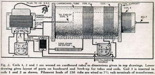
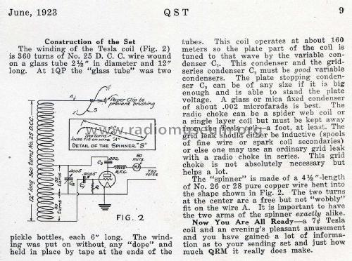
The hookup and layout of parts indicated in Fig. 2 should be followed to the letter to insure best results. Place the transformer at the left end of the baseboard near the rear. Then mount one of the sockets in front of it for the rectifying tube (281). To the right of the tube mount the fixed condenser. Mount the two coil supports to the right of the transformer. Then in front of this coil mount the remaining socket for the 210 oscillating tube.
Now comes the winding of the coils. First wind those called Coil 1 and Coil 2 on the 4-inch tube. These consist of 20 turns each of No. 16 DCC wire. Note the dimensions and spacings on the diagram (Fig. 2). Wind closely and tight and space them 1-1/4 inches apart. Wind in the same direction and secure the ends by any manner at hand. Wind in the same direction as the two former coils and secure each end to a bolt, the right hand one projecting out two or three inches from the end.
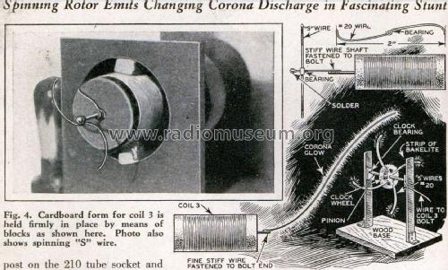
Mount the 4-inch coil in the supports as shown. Now slip the 800-turn coil (Coil 3) inside the larger tube and by means of blocking or little angle pieces, support it in the center of the large tube equidistant from all sides as illustrated in Fig 4. Solder all connections not secured by connectors or binding posts and make all leads as short as possible. Hookup wire can be either bare copper wire covered with spaghetti, or any type so long as it is well insulated and about No. 18 gauge.

Start with Coil 1. Connect the outside lead to one side of the fixed condenser and to one side of the filament winding used to light the rectifying (281) tube. The inside lead of Coil 1 then connects directly to the plate terminal on the 210 tube socket. Now connect the inside lead of Coil 2 to the grid binding post on the 210 tube socket and connect the outside lead to one end of the grid leak resistor. Connect the other side of the grid leak to the inside end of Coil 3 (next to the transformer), to the iron core of transformer to filament post of 210 tube, to one side of the high voltage winding on the transformer and remaining side of fixed condenser. The remaining side of the high power winding is then connected direct to the plate of the 281 tube. Each filament winding is then connected to the filament terminals of the two tube sockets. This completes the wiring. The transformer primary should of course be provided with a cord and plug.
To test first plug in the transformer. This will light the tube filaments. Then, to see if the high voltage is energizing the Tesla coil, run a screwdriver or other metal tool up and along the bolt at the protruding end of Coil 3, as demonstrated in the photo on page 92. It should draw sparks as it passes over the threads and will prove it is working. If no show of energy occurs go over the wiring thoroughly (first pulling the plug) and look for disconnected wires or poorly soldered joints. When properly hooked up it will surely work and you are then ready for a number of highly fascinating experiments.
With your Tesla coil operating properly you are ready for some of the most weird and interesting experiments imaginable. First, do not fear a shock. Slight burns may result if taken on the bare flesh but if one holds a metallic object in the hands no sensation is noticeable. Therefore, there is no danger.
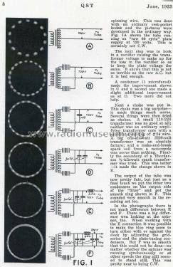
First let’s see what can be done about drawing a spark from the bolt on Coil 3. Hold a metal tool in the hand and gradually bring it near the bolt. When the breakdown distance is reached sparks will jump between the two metals similar to lightning. Too great a voltage must not be used, but any voltage from 350 up to about 750 volts is perfectly safe.
Now let’s try a little experiment with an electric light bulb. If you can get hold of a bum one so much the better. First fasten a small metal ball to the end of the bolt. Then, holding a 15 or 20-watt bulb by the glass, bring the metal ferrule near the bolt. As it approaches it will commence to glow and change colors according to the gas in the bulb and the power of the coil. Get a bulb in the “Five and Ten” marked “made in Japan” if you want to see some fascinating effects.
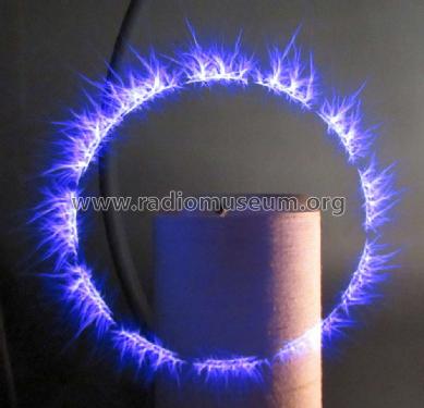
Here is another fascinating demonstration. Fasten a very fine, stiff wire to the bolt and bend it up and outward in a wide curve as illustrated in Fig. 5 (besides in fig. 4). Plug in the coil and watch the result in a darkened room. Varying the output voltage will change the glow around the wire and at the very end will be seen a very concentrated discharge of fire.
Here is one of the most spectacular stunts of all. It is a rotor spinning from the high frequency oscillations and emitting a changing corona discharge ever fascinating and beautiful. Bend a piece of fine wire such as No. 22 or 24 into a wide S as shown in Fig. 5. Slip this over a piece of stiff wire fastened to the end of the bolt horizontally. The wire must rotate freely and be free from kinks or corners. Start the coil and watch the S wire spin. It will rotate at terrific speed well up into several thousands of R.P.M. All around the circle will be seen an even number of brush discharges and the peculiar thing is that they will always be an even number.
Here is a way to mystify the crowd. Hold a match head near the bolt. No effect is noticed. Then wet the head so it is soaking. Hold it near the bolt again and it lights! The dry head was non-conductive but the wet head acted as a metallic conductor and soon ignited from the spark produced. Done with the bolt and coil hid behind a thin partition makes the trick doubly mysterious.

As the user becomes accustomed to the action of his Tesla coil he will discover many more interesting and instructive uses for it. Common things can be utilized to produce many weird results and spectators will never tire of watching the effects of its action. As before stated, there is not the least danger in its effects. But, don’t get careless with the direct output of the transformer itself. The current produced is at a much lower frequency (60 cycles) and 500 volts or more at this frequency will give quite a kick if taken through the body.
Ernst Erb, 22.Nov.15