Romance FM 1961
Schneider (Frères, Radio-Télévision); Paris, Ivry / Seine
- Country
- France
- Manufacturer / Brand
- Schneider (Frères, Radio-Télévision); Paris, Ivry / Seine
- Year
- 1961/1962
- Category
- Broadcast Receiver - or past WW2 Tuner
- Radiomuseum.org ID
- 218619

Note space where EB91 is on earlier versions


Catalogue 1962
- Number of Tubes
- 7
- Number of Transistors
- Main principle
- Superheterodyne (common); ZF/IF 480/6750 kHz; 2 AF stage(s)
- Tuned circuits
- 5 AM circuit(s) 6 FM circuit(s)
- Wave bands
- Broadcast, Long Wave, Short Wave plus FM or UHF.
- Power type and voltage
- Alternating Current supply (AC) / 110; 125; 145; 220; 245 Volt
- Loudspeaker
- 2 Loudspeakers
- Power out
- 3 W (unknown quality)
- Material
- Wooden case
- from Radiomuseum.org
- Model: Romance FM 1961 - Schneider Frères, Radio-
- Shape
- Tablemodel with Push Buttons.
- Dimensions (WHD)
- 500 x 340 x 230 mm / 19.7 x 13.4 x 9.1 inch
- Notes
-
4 gammes d'ondes : OC de 16.4 à 52 m, GO, PO, et FM de 87 à 101 MHz. Dispositif "loupe OC". Cadre à air blindé orientable et antenne FM incorporé. Deux HP, un elliptique de 16 x 24 cm et un statique.
Ce modèle est similaire au Romance FM 59 sauf le position du bouton pour l'orientation du cadre.
Differences to earlier "Romance FM"
- "Cadre" (loop antenna rotation control) moves from front to side
- Bass and Treble controls (earlier versions have a single tone control at volume and loop rotate at tuning side)
- Hole in chassis where EB91 is on older versions. Tag strip has 2 x OA79, but not same circuit
- VHF-FM head is ECF82 (as per other Schneider sets, but other older "Romance FM" sets use ECC85)
- Audio P.A. is EL84 (9 pin B9A, Noval), Earlier "Romance" and "Romance FM" use 6AQ5 (EL90).
Features (common to many Schneider Models 1956 to 1961)
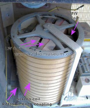
Large drum (Cadre, lit. Framework) with LW & MW loop aerials, screened with 3rd coil and rotatable. Separate Wavechange buttons for MW Loop, MW ant, LW Loop, LW ant
Separate AM and FM tuning scales/cursors and knobs
Entire VHF-FM scale is fine tuning on SW (OC Loupe lit SW magnify) of about +/- 50kHz using additional coil in VHF head only connected to SW L.O. circuit.
Dual gang 1M Ohms used for volume, connected to Tone controls for automatic loudness compensation. Pickup/gram input and switch.
- Net weight (2.2 lb = 1 kg)
- 8 kg / 17 lb 9.9 oz (17.621 lb)
- Mentioned in
- -- Original prospect or advert (Catalogue 1962)
- Author
- Model page created by Michael Watterson. See "Data change" for further contributors.
- Other Models
-
Here you find 262 models, 215 with images and 134 with schematics for wireless sets etc. In French: TSF for Télégraphie sans fil.
All listed radios etc. from Schneider (Frères, Radio-Télévision); Paris, Ivry / Seine
Collections
The model Romance FM is part of the collections of the following members.
Forum contributions about this model: Schneider Frères,: Romance FM 1961
Threads: 3 | Posts: 4
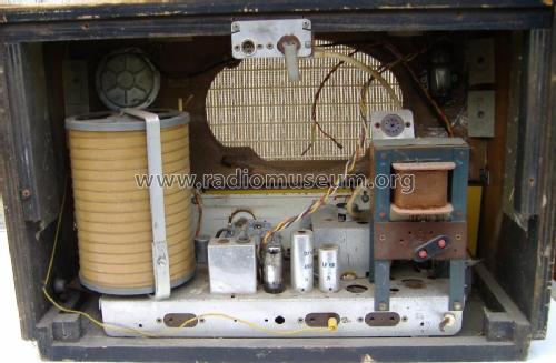
I call this a "repair" rather than restoration as I have no circuit, no back, no speaker, most tubes missing, Model and Tube line up unknown. The case is a little rough. It was part of a Lot I bid on for the Ultra "Twin 50", so in a way it was "free". No extra postage as it was an Auction in Ireland.
Stage 1
Schneider “Romance FM”
Yes, that's what is on the front! The “stages” are roughly different days, some days might have more stages though.
But.. the valve line up is a problem ( ) means missing
VHF( ) Noval
Mixer/Osc: ECH81 / 6AJ8 (but plugged into the IF position)
IF ( ) Noval
?? ( ) B7G
O/P EL84 (yes it's connected to audio transformer)
Magic Eye EM81
Rectifier ( ) (on top of transformer)
Chassis is stamped 1961 below the switch unit at the front.

That’s an ECH81 between the two IFT cans. Can’t be right!
The main elliptical speaker is missing.
I thought it was the Schneider Romance FM 1958
But impossible
Valves / Tubes 8: ECC85 ECH81 EBF89 EB91 EM81 6AU6 6AQ5 EZ80
The main chassis has only 4 sockets, one is B7G. There are 3 other valves Magic Eye, Rectifier and FM head. Intriguingly there is a punch out for a 5th base, but it definitely never had one.
It's got a pair of OA something maybe for FM discriminator. Maybe the b7G is an EBC91?
Maybe it's the case and chassis of two different sets? The speaker is missing.
Any ideas what schematic and what missing tubes? Underneath looks original
They do seem to use the 6AU6 RF/IF as an audio pentode on some Romance sets
It's B7G = EF94
So then there needs to be a 3rd diode somewhere else.. EAF80, EBC80, EBF85 for IF?
The Romance FM (1958)
8: ECC85 ECH81 EBF89 EB91 EM81 6AU6 6AQ5 EZ80
So the two OAxxx diodes replace the EB91 (hence tag strip with them is under unused socket hole)
The higher power EL84 replaces the 6AQ5 = EL90
So my best guess
7: (ECC85) ECH81 (EBF89) EM81 6AU6 EL84 EZ80 (maybe EZ81)
The two OA somethings definitely replace EB91.
There is a French thread discussing EL84 vs 6AQ5 (plus de puissance = More Power!) in relation to Schneider Romance but no schematics or other tubes mentioned
There are two 1958 Schneider models on Radiomuseum with
9: ECC85 EF89 ECH81 EBF89 EM81 EB91 6AU6 EL84 EZ80
The 6AU6 = EF94 is used only as Audio preamp. The EF89 is RF preamp, a deluxe feature... So take out the EF89 and the EB91 is logical for my model.
There is a Romance (1959) with no FM on Radio Museum. But no Romance FM (1959) though a picture of one on a French site doesn't look like mine.
I wonder is mine a later Romance FM in the 1958 cabinet?
Anyway what you think of the screened turning Loop Aerial Drum? I never saw that before!
Stage 2
After studying as many Schneider schematics as I could find:
The missing IF is certainly EBF89
Some (many?) Schneider sets did use 6AU6 (EF94) RF Pentode as audio preamp driving an EL84. A 6AU6 does make gram input work.
The missing VHF "head" might conceivably be an ECF82 and not the common ECC85
I decide the line up is either
ECC85, ECH81, EBF85, 6AU6(EF94), EL84, EM81 and EZ80
or
ECF82, ECH81, EBF85, 6AU6(EF94), EL84, EM81 and EZ80
Eventually after "Raiding" my friend's valve stock and borrowing the VCM162 to test them I get very weak LW from signal generator (Thanks Albert Lahoud).
Stage 3
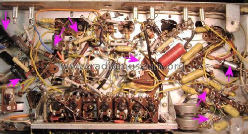
Three smaller "hunts" style caps cracking up so replaced as is 2nd HT capacitor and EL84 cathode decoupling. RTE1 on LW and hiss on VHF. Swap the ECC85 for ECF82 and Local FM stations... But it fades away.
Find two more dodgy HT Electrolytic capacitors and radio bursts LOUDLY to life!
See the photo at the model of replaced capacitors

Capacitors replaced
So differences with 1958 Schneider "Romance FM" identical case
EB91 --> 2 x OA79 makes sense
6AQ5 --> EL84 makes sense
But why swap from ECC85 to ECF82?
The giant funky drum does work on LW as rotatable directional aerial. Presumably MW too (try at night).
Stage 4
I had to redo the AM drive cord which is a pig.

Fortunately it's virtually identical to 1958 Romance FM. (The Chassis has a "1961" stamped on it)
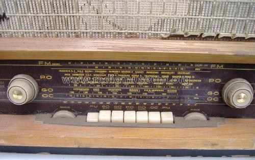
The Radio has separate AM & FM drive knobs and scale pointers.
Amazingly the entire VHF-FM scale is a + & - 50 (KHz?) "band spread" on SW.
The LW & MW both have piano key positions for External Aerial and internal loop (Cadre = lit. framework)
GO = LW
PO = MW
OC = SW
FM scale marked also "OC Loupe" lit. "Magnifying"
Now to figure out alignment with no service info. Too many coils and the schematics for Schneider sets show simply a dotted box for the switches and coils.
Now I need a new EM81 (not a glimmer) and an Elliptical speaker. The alignment first as it's badly out.
Stage 5
Repairing the VHF Head
The performance on VHF-FM was strange. A strong station was beautiful. But a weak station would have a fistling and whistling with distortion.
The IF on this set is marked on one can as 6.75MHz (I've seen 6MHz, 6.5MHz, 68MHz and 44MHz as well as the "normal" 10.7MHz).
I started with the IFT on the VHF head (carefully) and it suddenly went dead. Swapped ECF82 and just the same. LW/SW/MW ok. I peered at the lurking VHF head and pondered what to do. I could see two of the litz wires on the IFT to tags for o/p coax to main set from "open" side of the unit. They looked OK but I resoldered.
Still dead.
Examination suggested the screws on the valve base/screening can base + three solder joints held cover on. Indeed the screws are on pillars on top of a valve socket under chassis.

I scored solder joints with knife blade and a slight twist of screwdriver blade in joint and the joints one after another spring free.
The reason for the silence was immediately obvious. The Primary winding between an Anode on the ECF82 (no idea which, but likely the triode is oscillator and Pentode is mexer/IF out) and the HT was missing about 5mm of Litz wire at the HT side.

I'd guess it was rubbing against the underside of the cover, or was damaged originally and gradually disintegrated.
I added a fine piece of solid wire putting one turn on the "peg" of the coil former using fine nipper nose pliers.
Then with a hook made of the wire and very pointy tweezers I put 3 turns of the end of the Litz wire going to coil around it and "dressed" the remaining Litz wire along the solid wire. I soldered then till I could smell the coil former starting to protest.
The VHF is now nearly perfect (helped by a piece of Lidl coffee tine replacing the missing valve screening can.
I gave the IF chain a quick check by unplugging the ECF82 and connecting the Signal generator to the tags on the VHF Head IF out at 6.75MHz.
Stage 6
The case is missing the elliptical speaker so I cut off two edges on an old 8" Speaker, the remaining one from a pair on an "Amstrad" not-really-HiFi system dumped 30 years ago and someone gave me the remaining speaker about 12 years ago. It fits now in space for the elliptical on the Romance FM. I used the cutting wheel on the Dremel. Minimal dust as it "burns" away the steel. This is just temporary till I pick up a cheap elliptical speaker to fit properly so I slipped heavy corrugated card under the speaker to block the two spaces on either side.
Stage 7
Repairing the On/Off switch.Faulty On/off Switch
The on/off mechanism is just too poor quality. The pillar with the actuator is loose and thus the the spring pushes the actuator past the stop and the switch opens again.
So since it's a strange dual gang pot with a long shaft I decided to put a microswitch. The NC contacts which open when the lever is depressed is used.
Here is the spindle about to turn off

Here the switch is pressed, i.e. off

The edge of the case cut open and hole at "pot" enlarged. The microswitch lever was bent to poke thorough the hole and engage with the plate on rear of pot and put in place with rapid epoxy.
My espresso maker failed because the microswitch fell to bits. I'd bought a pack of 10 decent ones not long previous for not much different to one in Maplin and they were same size. The Espresso maker working now 3 years. So likely it will be reliable on the radio. Of course I forgot to refit the insulation ring and end stop ![]() so the back has to come off the pot. Fortunately I think I can do this without disturbing the nicely working microswitch or the wiring. I have a little "dinge" in case for shaft lever to catch on so it stays in off position.
so the back has to come off the pot. Fortunately I think I can do this without disturbing the nicely working microswitch or the wiring. I have a little "dinge" in case for shaft lever to catch on so it stays in off position.
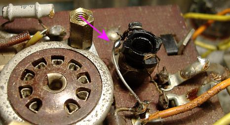
Here is the "repaired" Dual gang 1M Ohm log volume control

Arrow points at Microswitch epoxy glued on rear of volume control. Note dual gang 1M Ohm even though a Mono set!
The replaced parts

The one in a plastic tube with tar like ends was across the mains.
The 25uF 30V was on EL84 cathode. Replaced with Military grade 22uF 25V Metal can Tantalum. The other three electrolytic were HT decoupling.
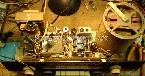
Top view of chassis

Performance
It sounds fine with my "chopped" 8" speaker (original elliptical missing) and the original electrostatic tweeter. The Bass and Treble controls work well
The unusual "Cadre" (Rotating drum with LW and MW loops at right angles X and Y and 3rd sceen loop on outside in Z direction) works very well for R4 LW (day & night) and R.Scotland MW (night).
The VHF is prone to a "whistle" when not tuned to a station and doesn't seem very sensitive. I'll check the ECF82 later. But with medium strength stations seems fine.
The Shortwave is awesome on just 2.5m of wire over curtain rail. The entire VHF dial is about +/- 50KHz bandspread (100KHz) (A Yaesu FT101 does about 500KHz per band), so you have "full" bandspread no matter what part of SW band the main AM dial is set (FM labelled also "OC loupe" = SW magnifier). SW reception seems very good and stable.
Considering this set came with only EM81 (dead), EL84 (tests good) and a faulty ECH81 incorrectly plugged into the IF tube socket, I'm very chuffed to have got this "thrown in" the lot I bid in a local auction to get the "Ultra Twin 50" I'm even more pleased to get it working without any documentation of valve lineup or an accurate schematic. The EBF89, 6AU6, replacement ECH81 and ECF82 (along with ECC85 to try) came from Member Albert Lahoud.
Michael Watterson, 10.May.12
This is different from the 1958 Romance FM, but in the same case and using the same metal chassis including hole for unused EB91.
Schneider certainly did things differently
- Dual MW & LW loops at right angles in a drum with 3rd screen loop. Turned by knob on side of set
- 6AU6 + EL84 O/P (1958 version Romance FM uses 6AQ5 rather than EL84)
- Dual 1M gang pot for volume part of tone network
- ECF82 VHF-FM Head (1958 version Romance FM uses ECC85)
- 6.75MHz rather than 6.5 or 10.7 for FM IF
- No Schneider schematic shows the switch unit wiring and L.O. coils, just a box labelled "Bloc"
- EBF89 is FM detector and 2 x OA79 for AM Audio and AGC ((1958 version Romance FM uses EB91 instead of 2 x OA79)
- One combo AM & FM IFT can, but separate AM & FM IFTs elsewhere
- An "extra" FM IFT (6.75MHz) that looks like a low pass filter between IFT on o/p of ECL82 Pentode(the mixer) and the ECH81 Hexode used as a 6.75MHz IF on FM but mixer on AM (that's normal, it's the extra IFT that is unusual with tuning access only on bottom, closed top), despite looking like a LPF it peaks on 6.75MHz
- Entire VHF-FM dial is about + & - 50KHz fine tuning on SW band. Done with an extra variable coil inside the VHF head but only connecting to HF band L.O. on the main chassis ECH81
Tube line up
The Magic Eye is EM81
ECF82, ECH81, EBF89, 6AU6, EL84 and an EZ80 or EZ81. This was based on studying Schneider circuits, logical deduction and plain guess / trial (ECC85 tried then ECF82 for VHF head).
Schneider seem to especially like EBF89 (IF + Detectors) and 6AU6 (RF Pentode used as AF preamp) combo which doesn't seem common?
Audio stages of 1958 version of Romance FM
.png)
A comment made to me:
I've never seen NFB to the screen grid before! Also, the 6AU6 appears to be operating without any bias (the cathode is grounded and so, indirectly, is the grid).
The 6AU6 = EF94 and is about -1V or less vs -2V to 3V for EF93, EF95. I tested the EF93, 6AU6, an actual EF94, EF95 and E95F on the VCM163. The anode current is very sensitive to g2 volts. So at 0V Vgk with a low screen (g2) the Anode current can be "normal". Note the g2 is fed from anode but with AC decoupled
Bright orange is main HT
Orange is secondary HT filtered by 2k2 and 2nd capacitor
Brown is DC feedback from 6AU6 anode to g2
This shows that there is
1) Essentially DC feedback from Anode to g2 of 6AU6
2) AC feedback via tone control to g2 AND g1 from output at the speaker. The version I have is EL84, but circuit looks similar. Except it has Treble and Bass.
The Schneider models using EL84 are similar
The above schematic is an edited version of a different Schneider that uses dual gang pot for volume and 6AU6 + EL84. But it's not the same, hence I "greyed out" part.
Dual gang pot for Mono Volume Control
A comment made to me:
The dual gang pot looks like it has been fitted as an alternative to a tapped loudness control.
It's a feature of almost all the Schneider designs 1956 to 1959 I looked at. It's not used the same way as most tapped pots. The 1st pot near panel is fed with Audio via a screened cable. It's wiper goes to "maximum" end of 2nd pot beside switch (directly on all schematics I have seen, but my set has a 1 K resistor). The minimum end of 2nd pot is fed from tone control network which has a Bass and Treble control and is fed from the EL84. The wiper feed 6AU6 grid via a capacitor on screened cable.
The volume control is somehow feed from a Bass & Treble control in a feedbank network as well as the input. The Bass & Treble work well.
As well as the two screens on the 1st pot "earthy end" there is a wire going to "earthy" part of tone control cable. So the Dual pot has 2 wires (one signal & 1 "earth" from tone feedback) and two screened cables.
it's not an arrangement I've seen. It's obviously a deliberate DESIGN time alternative to a tapped pot. I suppose a single gang 470K pot and the tone feedback and audio in both via 470K resistors to "top" of pot might work...
An apparently puzzling feature is that many Schneider schematics (1956 to 1958) show only one tone control even when a photo appears to show Treble and Bass. (Romance FM 1958)
However close examination reveals that the 2nd knob on the right of piano keys is labelled "Cadre" (= framework , i.e. Frame or loop aerial), a knob to rotate the loop aerial. My model (stamped 1961 on chassis and VHF head) has a slightly larger Schneider badge and the "Cadre" knob is at the side. The front knob to right of piano keys is in fact Treble, like on German sets.
Here is close up of the "drum"

The outer "screen" wire could be used to pickup local interference and "cancel" or as a sky wave aerial on HF, but I think it's just a screen to reduce local E field pickup by MW & LW coils.
PO (MW) & GO (LW) each have a "Cadre" and "Ant" pair of piano keys. OC (SW) and FM just have one key each. There are two families of "Romance",
AM only = "Romance"
AM + FM = "Romance FM"
Michael Watterson, 10.May.12
Points of Difference with “Romance FM ‘58”

1) AM only versions don't have "Romance FM" badge
2) Larger flatter "Schneider" badge than"Romance FM" '58 (though this might not be accurate)
3) Earlier versions have "Cadre" (loop rotation control) here. This has Treble control there
4) "Cadre" (loop rotation control) moves to side (not on earlier versions)
5) Hole in chassis where EB91 is on older versions. Tag strip has2 x OA79, but not same circuit
6) VHF -FM head is ECF82 (as per other Schneider sets, but other older "Romance FM" sets use ECC85)
7) Audio P.A. is EL84 (9 pin B9A, Noval), Earlier "Romance" and "Romance FM" use 6AQ5 (EL90). An earlier FM model (not "Romance" but this Symphone '58 uses EL84, but ECC85 rather than ECF82 and has a EF89 AM RF premap / extra FM IF)
All of the “Romance” and “Romance FM” models I've seen earlier than 1961 are 6AQ5/ EL90 o/p tube, a B7G. Some late German sets do use a EL95 rather than EL84. Schneider seem to use EL90 or EL94
Other Schneider models do use the EL84. (but not any "Romance" variants I've seen)
This "Romance FM" is definitely after 1958, probably not the '59 version (I found a Romance 59, but it's AM only and still uses 6AQ5, it's likely using the EBF89 diodes for AM, hence no EB91). Since Chassis & VHF head is stamped 1961, and uses 2x OA79 rather than EB91of all earlier models it's likely a "Romance FM" '60 or '61 model.
The Schneider Beethoven '59 is ECF82, EBF89, 6AU6, EL84 and EZ80. But adds EF89 AM Preamp/FM IF and a EM84 instead of a an EM81 Magic Eye. Also has EB91 rather than 2 x OA79.
So this confirms my suspicion this is"Romance FM" '60 or '61
Probably NOT a "Romance FM '60" but must be a "Romance FM ‘61"
Someone has a 1960 model with EL90 (6AQ5):
Recherche du schéma du Schneider Romance FM 1960
Il y a quelques temps, j'ai posté un sujet sur un Schneider Romance FM de 1960 ou (61 ?). Il m'a donné plusieurs heures de bonnes réceptions mais le support du tube de la finale EL90 a mal vieillit et produisait des faux contacts de plus en plus fréquemments.
[Trans: Some time ago, I posted a topic on a Schneider Romance FM 1960 or (61?). It gave me several hours of good reception but support the tube EL90 has the final ageing and poorly produced bad contacts increasingly often.]
His can't be a '61 because mine is definitely made in 1961 and has EL84 (9pin), not 6AQ5/EL90 (7pin)
Several French forum threads mention a “Romance FM” 1961 version with EL84 rather than the 6AQ5 on earlier models. Plus Puissance!
Conclusion
It is no later than 1961 due to stamps on chassis and VHF-Head. The Earlier "Romance" including 1960 produced model are all 6AQ5 / EL90 rather than EL84. All FM models up to 1959 at least have EB91 as well as EBF89 rather than 2 x OA79 germanium diodes. Thus this is identified as a "Romance FM" 1961
Michael Watterson, 10.May.12