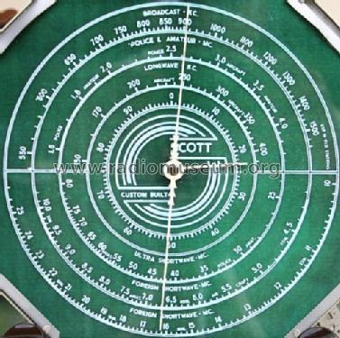
Pointer dial Philharmonic Chrome CHASSIS
Scott Radio Labs.(E.H., Transformer); Chicago (IL)
- Country
- United States of America (USA)
- Manufacturer / Brand
- Scott Radio Labs.(E.H., Transformer); Chicago (IL)
- Year
- 1937
- Category
- Broadcast Receiver - or past WW2 Tuner
- Radiomuseum.org ID
- 55372


USA Scott Philharmonic (only AM) No E-651

Scott Philharmonic

Collection privée (réf.: 1780)

aus ebay, mit Erlaubnis des Verkäufers mono
aus ebay, mit Erlaubnis des Verkäufers mono

aus ebay, mit Erlaubnis des Verkäufers mono

aus ebay, mit Erlaubnis des Verkäufers mono

aus ebay, mit Erlaubnis des Verkäufers mono

aus ebay, mit Erlaubnis des Verkäufers mono

aus ebay, mit Erlaubnis des Verkäufers mono
aus ebay, mit Erlaubnis des Verkäufers mono
Collection privée (réf.: 1779, 1780)
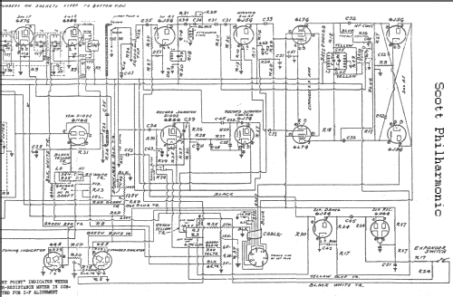
Click on the schematic thumbnail to request the schematic as a free document.
- Number of Tubes
- 30
- Valves / Tubes
- 6U7 6U7 6L7 6E5 6E5 6K7 6K7 6K7 6B8 6J5 6J5 6L7 6L7 6J5 6J5 6J5 6B8 6B8 6H6 6B8 6J7 VR150 6J5 6N6 6L6 6L6 6L6 6L6 5Z3 5Z3
- Main principle
- Superheterodyne (common)
- Wave bands
- Broadcast, Long Wave and more than two Short Wave bands.
- Power type and voltage
- Alternating Current supply (AC)
- Loudspeaker
- 3 Loudspeakers / Ø 15 inch = 38.1 cm
- Material
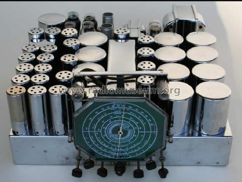
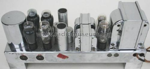
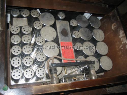
- Metal case, TUBES VISIBLE
- from Radiomuseum.org
- Model: Pointer dial Philharmonic Chrome CHASSIS - Scott Radio Labs.E.H.,
- Shape
- Chassis only or for «building in»
- Notes
- Speakers: 1 bass and 2 optional tweeters. Dynamic expansion. Introduced in April 1937.
- Price in first year of sale
- 275.00 $
- External source of data
- Ernst Erb
- Source of data
- The Radio Collector's Directory and Price Guide 1921 - 1965
- Circuit diagram reference
- Rider's Perpetual, Volume 14 = 1944 = before 1943
- Mentioned in
- A Flick of the Switch 1930-1950 (Pre War Consoles)
- Literature/Schematics (1)
- E.H.Scott Radio Collectors Guide (1925-1946)
- Literature/Schematics (2)
- Pre-War Consoles
- Other Models
-
Here you find 198 models, 122 with images and 48 with schematics for wireless sets etc. In French: TSF for Télégraphie sans fil.
All listed radios etc. from Scott Radio Labs.(E.H., Transformer); Chicago (IL)
Collections
The model Pointer dial Philharmonic is part of the collections of the following members.
Forum contributions about this model: Scott Radio Labs.E.H: Pointer dial Philharmonic Chrome CHASSIS
Threads: 1 | Posts: 1
Fellow Radiophiles:
Richard Majestic published in the American magazine Antique Radio Classified (Vol 29, No 12, December 2012) an extensive article on his experience with the Scott Philharmonic 30-Tube receiver from 1937. Richard has kindly consented to have his fine article republished here. Richard explores with great technical detail the many performance details and operational features of this luxury model. He also tackles an original design flaw in the Automatic Gain Control (AGC) system that causes severe distortion in the IF stages.
Thank you Richard for such a fine article.
-Joe
Ernest Erb, June 28, 2013:
We are sure and it was also said at the Annual Convention of the the Mid Atlantic Antique Radio Show (I was not there) in this month, that there is no "original design flaw in the Automatic Gain Control (AGC) system that causes severe distortion in the IF stages.". It is a question of proper values and places for them to function without any problems.
The EH Scott 30-Tube Philharmonic Radio Receiver by Richard Majestic
 |
The 1937 EH Scott 30-tube Philharmonic receiver included a lot of features, as standard. It had a continuously variable intermediate frequency (IF) bandwidth for ‘high fidelity’ frequency response, two independent AGC circuits, a 20dB bass boost circuit, a volume expander, a phonograph scratch and noise reduction circuit and push-pull parallel 6L6 audio output circuit with negative feedback. The Philharmonic had two tuned radio frequency (RF) stages, one is switched out on the highest short wave (SW) band and four IF stages. The audio IF response was continuously variable and claimed to be flat topped at all points, from between 4 kHz and 32 kHz band width; this allowed 16 kHz audio bandwidth. Sensitivity was claimed to be 0.5 microvolts on all but the highest SW band. The IF band width was front-panel adjusted by a control mechanically linked to variable capacitors on each of four IF stage transformers, that changed the center frequency of each IF’s primary and secondary, to accomplish stagger tuning. The Philharmonic employed both amplified IF automatic gain control (AGC) and delayed RF AGC. Each AGC voltage was separately derived by an amplified IF frequency tuned gain stage and rectifier. The use of IF tuned AGC amplifiers reduces the distortion effects of tuned station modulation of the IF AGC voltage. Dial calibration was claimed to be 0.2 per cent. The 1937 Scott Philharmonic, was quite advanced for 1937; EH Scott the master marketer was trying to out-feature Zenith, McMurdo Silver and to some degree Midwest.
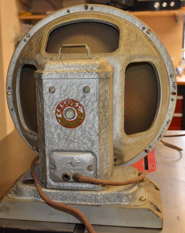 |
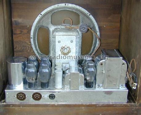
Audio processing was employed in the Scott Philharmonic. Besides the usual bass and treble controls and loudness compensated volume control, there was also a dynamic range expander and an automatic noise reduction system for the phonograph input. The tone controls are +-20 dB bass boost and -15dB control and 0 to -15dB treble cut control. The Philharmonic also has a 60 Hz notch filter to minimize hum when the bass boosted. The dynamic volume range expander is continuously variable and uses a “Magic Eye” tube to indicate the degree of expansion. And many electronics article described the 1937 EH Scott Radio Laboratory Automatic Needle Scratch Suppressor noise reduction system for the phonograph input as state-of-the-art. Other audio features of the Philharmonic were a 10kHz audio notch filter, a 40-watt class-A power amp employing push-pull parallel 6L6 output tubes, and a speaker system employing a 15-in. Magnavox woofer and two five inch Jensen cone tweeters.
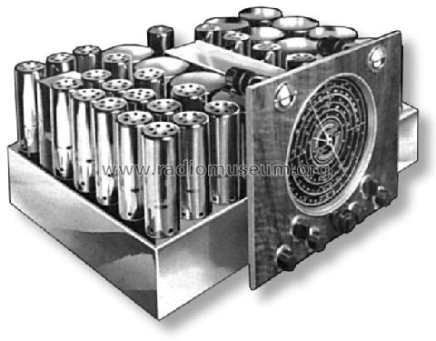
The set was constructed on two welded, heavy gauge steel, chrome-plated chassis, one for the tuner and control section and the other for the power supply amplifier section. Later versions included a third chassis, which contained an inductor-capacitor (LC) crossover network.
It should also be pointed out here that in 1936 EH Scott had, in limited production a tri-amplified receiver, one channel was used for 30-125 Hz, 100-600 Hz, and 3-16 kHz frequency bands. This set was the 40-tube unit, later a 48-tube, and still later a 57-tube, called the Quaranta. It employed an 18 inch woofer, two 12 inch midranges and three tweeters. A few Quarantas came equipped with a disc-cutting lathe and ribbon microphone and cost up to $5,000 in 1936-37. The Quaranta’s production was very limited. It should be noted that the Quaranta AM receiver started out as the All Wave 23, but with the additional audio circuits (tone, expander, noise reduction, recorder circuits, microphone preamplifiers), two additional power amplifiers and additional speakers and some of the most magnificent cabinets ever found in console radios.
The All Wave 23 also had the variable bandwidth that was transplanted into the Philharmonic and also had 4 IF amplifier stages but only one RF amplifier. It also used the new mutual coupling IF transformers, that also were utilized in the Philharmonic while the All Wave 12 and 15 used the capacitive coupled IF transformers. The only advantage to mutual coupling IF transformers are the ability to incorporate variable stagger tuning for variable bandwidth because both primary and secondary coils are in the same can and on top of the chassis, whereas the secondary was on top of the chassis in a can and the primary, most unturned below the chassis in the All Wave 12 and 15.
So where did all the New ‘Feature ideas’ Come From?
The use of multi-amplified AGC came from early communications receivers and was used as early as 1934 in the high end Zenith 1000Z Stratosphere radio that sold for $750. Overload of the 1st detector (mixer) was a common problem when strong local stations were tuned producing birdies or image like interference. The use of the pentagrid vacuum tube made electron beam mixing of the local oscillator (LO) with the incoming RF very distortion free but the LO level was constant but the incoming RF level was all over the place but the mixer needs close to equal levels to minimize distortion or spurious harmonics, so the RF section AGC was needed. It should be noted that the All Wave 23 used 2nd detector AGC for the IF strip and amplifier AGC for the single RF amplifier stage.
 |
Variable and wide bandwidth IF stages were first used in a 1933/34 Hammarlund receiver and in was used in the 1934 Zenith 1000Z Stratosphere radio. Both used the variable IF coupling transformers, the tuned secondary was moved closer or further away from the tuned primary. In 1936 McMurdo Silver was delivering a selectable IF bandwidth radio, 15kHz and the narrow 3.5kHz bandwidths. For the 15kHz wide bandwidth McMurdo used stagger tuning of a T3 and T4 IF transformers. EH Scott in the All Wave 23 and Philharmonic took stagger tuning one step further with continuously variable bandwidth IF, 3kHz to 16kHz. In the Philharmonic T1 and T4 were primary and secondary stagger tuned, one up the other down, while T2 and T3 both the primary and secondary were de-tuned, T2 up and T3 down in frequency. Scott used a jack shaft that ran under the four IF transformers, the shaft connected to variable air dielectric capacitors and setup so that some meshed and others un-meshed as the shaft is turned. This bandwidth shaft also adjusts a pot that is used to vary the AGC voltage in an attempt to keep the IF strip gain constant as the bandwidth is varied. Good in theory but I've never seen it work correctly. Zenith’s Stratosphere used the secondary amplified IF AGC to somewhat correct for the gain change with bandwidth. Another problem the Philharmonic has is the secondary amplified IF AGC is tapped off at the secondary of T3 IF transformer making the AGC less effective for gain equalization. In 1937/38 McMurdo Silver 1517 used three selectable bandwidths, accomplished by selecting three additional IF coil windings in the three primary and secondary IF transformers and used amplified AGC to compensate for the gain change with bandwidth.
The Bass Boost circuit used in the 1934 Zenith Stratosphere used inductors and capacitors tuned below 600 Hz and by mixing added or subtracted to the inter-stage audio transformer’s output, to provide bass boost or cut. The Philharmonic design is electrically identical for bass boost and they used variable resistance to load the audio coupling capacitor to provide bass cut. The Bass control is a dual pot, one for the boost and the other for cut, the center of rotation being flat response.
The volume expander was first shown in 1933 in some high-end radios but the identical design used by Scott was used in the 1935/36 McMurdo Silver Masterpiece V and used a pair of pentagrid tubes, in push-pull to modulate the audio level. The expander feature was incorporated to reverse the effect of audio compression being used by all broadcasters during this period.
The dynamic scratch and noise reduction for record playing was probably a first in consumer radio/phonographs and a first for Scott. Essentially the way it works is to detect fast rise time impulse noise and reduce the audio gain. The scratch filter dynamically reduces the high frequency response when high frequency noise is detected.
How Well does the EH Scott Philharmonic Actually Perform
 |
Recently I have restored three Philharmonic radios, two Beam-of-Light dial from 1940, one an AM/FM from 1941, the AM section is identical to the AM only radios. However, some engineering changes were made in the way the variable IF bandwidth was configured. One change that should have been made was the volume control which has the AC power switch and the Philharmonic consumes almost 400Watts so the switch fails and most radio shops don’t bother to put in the correct replacement volume control in that it had a 20% tap, used for loudness compensation.
 |
With two RF and four IF amplifier tubes, this radio is noisy unless the tubes, three 6K7G, two 6U7G and one 6B8G are new and selected noise free. I've been able to measure 0.5uV with 20dB S/N but this is after trying many NOS tubes looking for low noise tubes. The RF design and mechanical implementation is very good and the sensitivity across all bands is good. Typically I measure 10uV with a 30dB S/N. one of the claims-to-fame for EH Scott receivers dating back to 1932 was its immunity to external electrical noise, the Philharmonic is well shielded also and uses a beautifully designed shielded antenna coupling system that continues that early tradition.
The Philharmonic uses regulated 150VDC for the triode local oscillator but didn’t use any temperature compensation or the best oscillator circuit design so the radio drifts in the first ten minutes or so. Zenith and McMurdo Silver used temperature compensation capacitors and they have no drift.
The bass boost is a 2-pole filter design (12dB per octave) and is very effective and does sound very good. As a two pole filter the bass boost has less effect on the mid-frequencies while increasing the low bass below 600Hz. The 20dB maximum bass boost was incorporated to compete with the Zenith Stratosphere which had great booming bass from the two 12” Jensen A12s and the 50Watt triode power amplifier.
Engineering Corrections that will Make Your Philharmonic a Pleasure to Listen Too
 |
One major problem I’ve encountered when restoring these Philharmonics is the very high audio distortion from the detector, typically greater than 15% total harmonic distortion (THD). In looking into this problem with a 400MHz. oscilloscope connected to the plates of the IF strip, I found that on strong signal levels (greater than 100uV) the third IF amplifier overloads, badly distorting the IF envelope. This happens because the amplified IF AGC circuit is ineffective in reducing the gain of IF signal to prevent overloading the third and fourth IF stages. The IF signal level is so high that the grid is driven into grid conduction, causing non-symmetrical IF signal clipping or compression. The now distorted envelope is again amplified and further distorted in the fourth IF amplifier/final audio detector.
The cure, I borrowed from Mr. McMurdo Silver who encountered the same issue with his Masterpiece II and III which had three IF amplifiers and the simple 2nd detector AGC circuit; he put 100k resistors in series with each of the three IF amplifier grids which prevents over driving the grids which causes IF envelope distortion but does not reduce the overall IF strip gain with weak radio signals. So what I did was put three 100K resistors in the grid circuit of the three 6K7G IF amplifiers and re-align the IF entire IF section. This simple change reduces overall audio THD to less than 3%, this reduction is a very audible improvement.
 |
In the three Philharmonics I recently restored I’ve found the IF AGC circuits do not work as intended even though the AGC voltage rises to greater than -35VDC on mid-level RF signals (100uV) and without serious redesign I doubt this design would ever work correctly. The chief reason for this problem comes about because the replacement metalized polyester film capacitors I use are significantly better capacitors (lower ESR, lower inductance)than the cheap wax capacitors EH Scott used from 1937 to 1948. The better capacitors increases IF circuit gain, which is not needed. I did noticed that Scott engineers changed the bypass capacitor design by putting the three bypass capacitors in series instead of each all going to ground. Additionally, the IF transformers are so well designed they have high “Q”. In other words, their excellent engineering of those beautiful IF transformers created a problem for them and now the restorers. Take a look at my scope pictures, before and after my modification of the IF grids with moderate antenna RF signal level.
 |
The 100k grid series resistor trick does solve one issue but the overall problem, the poor amplified AGC circuit is still a problem, unlike the McMurdo Silver Masterpiece V, VI and 1517 which has a better design. EH Scott tried to correct this problem by removing B+ from the one of the RF amplifier screens when the bandwidth control is increased, thinking the listener will want lower distortion and not need high RF gain, this not only improves the bandwidth of the RF amplifier strip but it also reduces the RF amplifier gain which reduces the IF signal level reducing the audio distortion too. Reducing the overall gain of the RF or IF strip is not the answer since that will reduce the overall sensitivity of the radio but improvement in the amplified AGC circuit or improved vacuum tubes that have better gain control range would help to cure this design problem.
It’s also a historical fact that during this period the EH Scott company was having financial troubles and I’m sure unable to put additional engineering effort into correcting these design problems.
Final Review Comments
I recently had a McMurdo Silver 1517 on the bench and it outperformed the Philharmonic in selectivity, sensitivity, distortion and noise. The Philharmonic has more audio power but the original field coil 15” Jensen used by McMurdo in the 1517 does sound better than the original 15” Magnavox used in the Philharmonic.
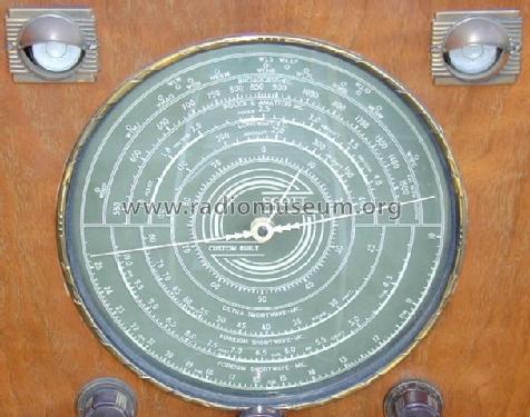
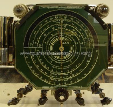
The shadow dial on the Philharmonic is very nice and makes tuning a frequency easy and parallax free.
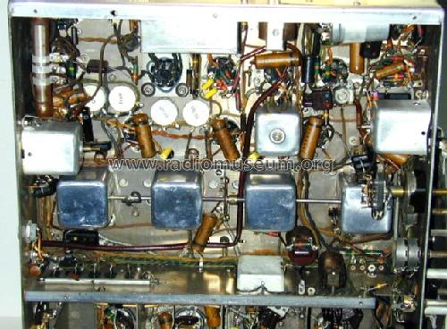
One major service problem is the 77 film capacitors and 10 electrolytics used in the Philharmonic, Scott used the cheapest capacitors made and they become leaky and often short-out. A good number of these capacitors are in the IF transformer cans on top of the chassis and not easy to change. Another group of capacitors are in the bass boost circuit and in a group of seven 0.47uF bypass capacitors Scott put in boxes that are potted with tar, good luck with changing those. Note in the picture the new bass boost components below the chassis.
Because the Philharmonic uses so many amplified stages it gets noisy as the tubes age and the noise reduces the effective sensitivity or usefulness of the radio for DXing. In broadcast band use this may not be an issue if the bandwidth control is advanced a bit.
The chrome on everything makes this radio a standout, but don’t handle the radio without wearing gloves. If you do touch the chrome with your hands, get the Windex out, spray the chrome and wipe it dry with a new paper towel, this is the only way to keep a Scott, McMurdo or Zenith chrome beautiful and corrosion free for another 76 years.
Tech Note: I measure the radio’s distortion using a HP 606A RF generator audio modulation from a Tektronix SG-505 oscillator set to 80% and the distortion measured with a Tektronix AA-501 distortion analyzer. Oscilloscope used is a Tektronix 2465 400MHz. The HP RF generator is 50 Ohms terminated and connected to the antenna input posts and the audio distortion analyzer is connected across the voice coil and the VC audio voltage set to 0.775VAC RMS with the volume control.
Richard Majestic has more than 30 years’ experience in broadcast television engineering system design and engineering management. He holds ten patents for digital servo system designs, cryogenic instrumentation, and low noise analog circuit designs. Richard and his wife recently unemployed (retired) moved to Las Cruces New Mexico, was elected President of the New Mexico Radio Collectors Club, a group of engineers and scientist dedicated to preserving early radio, television and computer products. Richard can be contacted at rmajestic(at)msn(dot)com or 575 521-0018
Joe Sousa, 30.Mar.13