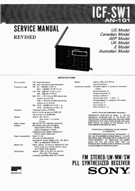
FM Stereo / LW / MW / SW Receiver ICF-SW1 - Type 1
Sony Corporation; Tokyo
- Country
- Japan
- Manufacturer / Brand
- Sony Corporation; Tokyo
- Year
- 1987–1993
- Category
- Broadcast Receiver - or past WW2 Tuner
- Radiomuseum.org ID
- 73732


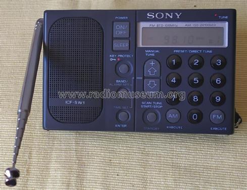


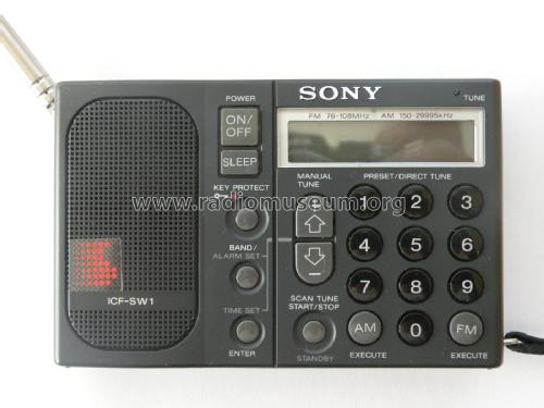
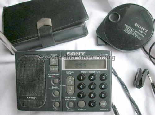

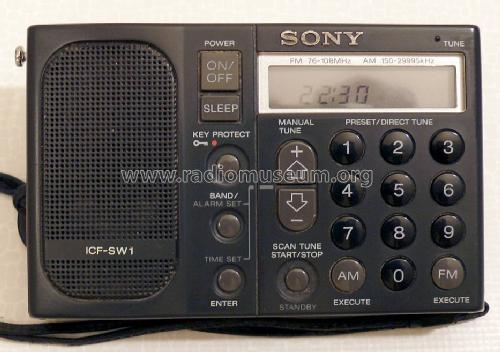
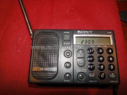
SONY ICF-SW 1 S


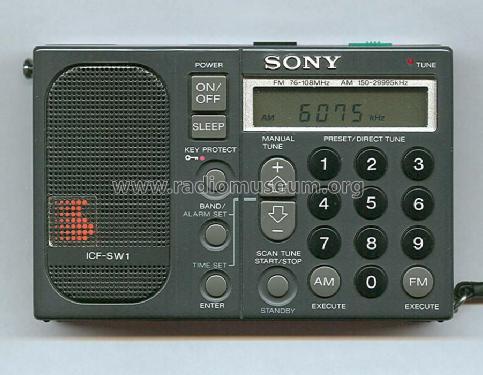
Sony ICF-SW1E
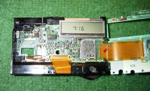
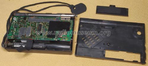
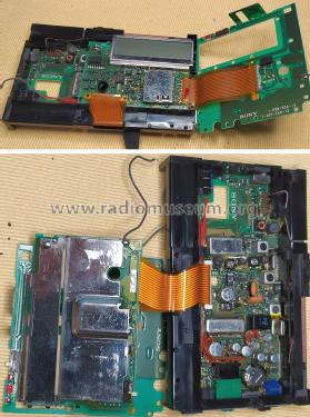
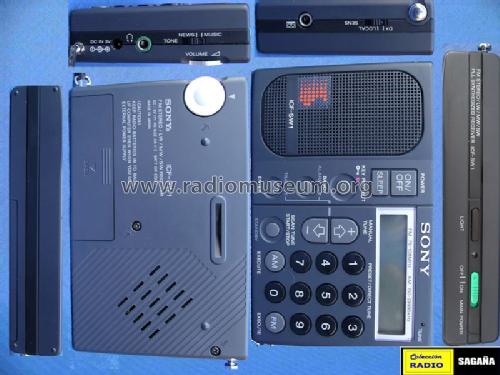
Blick ins Innenleben.
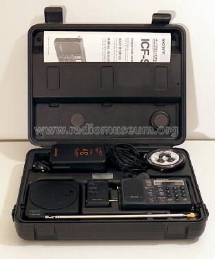

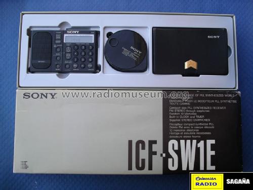
Set ICF SW1E

Set ICF SW1S

STS Archív.


STS Archív.
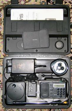
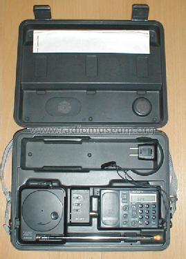
Sony ICF-SW1S - der komplette Koffer.


Click on the schematic thumbnail to request the schematic as a free document.
- Number of Transistors
- Semiconductors present.
- Semiconductors
- Main principle
- Superhet, double/triple conversion; 1 AF stage(s)
- Wave bands
- Broadcast, Long Wave, more than 2 x SW plus FM or UHF.
- Power type and voltage
- Batteries / addl. power jack / 2 × 1,5 / 3 Volt
- Loudspeaker
- Permanent Magnet Dynamic (PDyn) Loudspeaker (moving coil) - elliptical
- Material
- Plastics (no bakelite or catalin)
- from Radiomuseum.org
- Model: FM Stereo / LW / MW / SW Receiver ICF-SW1 - Type 1 - Sony Corporation; Tokyo
- Shape
- Very small Portable or Pocket-Set (Handheld) < 8 inch.
- Dimensions (WHD)
- 120 x 71 x 23 mm / 4.7 x 2.8 x 0.9 inch
- Notes
-
Type 1: MW: 530-1610 (selector 10 kHz) or 531-1611 kHz (selector 9 kHz),
LW: 150-528 kHz,
SW: 1,615-29,995 kHz.
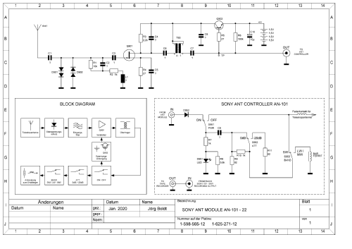
FM:76-108 MHz (Japan and CCIR).Zum Zubehör gehört u.A. die Ant-Module Wide Range Antenna AN101.
- Net weight (2.2 lb = 1 kg)
- 0.3 kg / 0 lb 10.6 oz (0.661 lb)
- Price in first year of sale
- 698.00 DM
- Source of data
- -- Collector info (Sammler)
- Author
- Model page created by Roland Müller. See "Data change" for further contributors.
- Other Models
-
Here you find 3913 models, 3773 with images and 947 with schematics for wireless sets etc. In French: TSF for Télégraphie sans fil.
All listed radios etc. from Sony Corporation; Tokyo
Collections
The model FM Stereo / LW / MW / SW Receiver is part of the collections of the following members.
- Vincent Baccialone (F)
- William Fague (CH)
- Salvador Galan-Ocaña (E)
- Francisco Gallego (E)
- Rudolf HEINZ (D)
- Ervé Leclercq (B)
- Wolfgang Lohrie (AUS)
- Jose Mesquita (P)
- Jorge Mochkovsky (RA)
- Kazuo Nishida (J)
- Ulf Olovson (S)
- Gerhard Platz (D)
- Jacques-André Ramelet (CH)
- Stefan Redlich (D)
- Heinz Schmidt (D)
- Peter Seifert (D)
- Sándor Selyem-Tóth (H)
- Davide Tambuchi (I)
Forum contributions about this model: Sony Corporation;: FM Stereo / LW / MW / SW Receiver ICF-SW1 - Type 1
Threads: 4 | Posts: 7
Hello fellow members,
My unit refuses to accept the FM band selection.
Pressing FM button seems to select FM band, but the frequency digits do not appear on the LCD. When presssing the Up or Down keys, the radio switchtes itself back to AM mode. EDIT: This behavior seems to be normal, as we need to type in a frequency in order to be able to commit the RF band selection. However, the radio was not accepting some digits, at least the ones I tried in my brief testing before dismantling the unit.
At least the AM seems to be working, showing the frequency digits, despite with apparent low sensitivity.
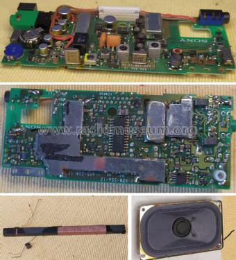
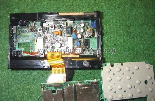
That said, the radio also shows the usual motorboating sound at the speaker (but not on headphones), typical of poor decoupling caused by the infamous SMD aluminium electrolytic capacitors that plaged so many equipment of that era.
Contrary to some public information, all SMD electrolytic caps should be replaced at once, not only those two directly afecting the audio power IC Filter and Bias 1 (C607 and C608).
Why? Because all were manufactured at the same time period using the same deficient manufacturing technology and soldered using the same perfectible technique, so all of them are suspect. Additionally, other operating conditions besides the obvious motorboating noise may be negatively affected by the other defective caps and overlooked at a summary analysis.
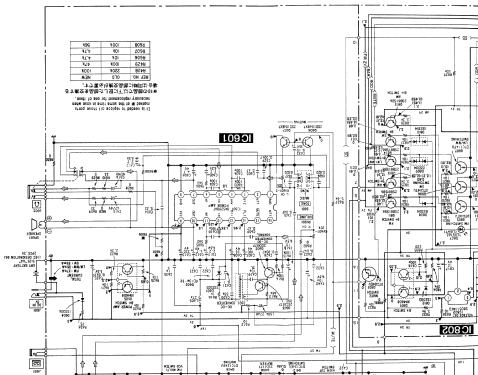
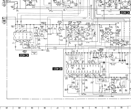
The six SMD electrolytic caps that would need to be replaced are:
| Part | Value | Used at |
| C420 | 220uF / 4V | IC401 CX20111 - VCC |
| C613 | 220uF / 4V | IC601 BA5208AF - VCC |
| C607 | 100uF / 4V | IC601 BA5208AF - FILTER |
| C608 | 33uF / 4V | IC601 BA5208AF - BIAS 1 |
| C426 | 47uF / 4V | Q413 - BASE |
| C431 | 47uF / 4V | IC402 LA3335M - VCC |
In my unit, C420 220uF for VCC decoupling of the IC401 CXA20111 RF IC have leaked as well as the others.
I ordered new capacitors from my local shop and wating for delivery.
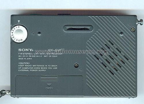
The battery contacts also shows signs of corrosion.
As usual, I will clean the PCB's and keyboard membrane with proper IPA spray to remove any electrolytes and other residues.
I hope this would solve the above FM band selection issue, otherwise it seems I will have a troubleshoot session ahead.
As for the battery contacts, I use cleaning vinager with good results.
(to be continued)

Jose Mesquita, 14.Aug.22
Entgegen der Meinung in diversen Foren sind nach meiner Erfahrung immer alle 6 SMD-Elkos schadhaft. Es handelte sich damals bei Sony um ein Technologisches Problem beim Reflow-Lötprozess bei dem wohl die Temperaturbeständigkeit der neu verfügbaren SMD-Elkos falsch eingeschätzt wurde. Im Langzeitverhalten zeigten sich undichtigkeiten der SMD-Elkos. Das Schadensbild zeigt sich erst bei entfernten Elkos, vorher war es durch die kleinen Kunststoffsockel der Elkos nicht erkennbar. Also optische Prüfung der Platine bringt nichts.
Fazit: alle 6 Tauschen und fertig ! klein groß
Ein großes Foto vom Schadensbild ist oben im Bilderordner.
Stefan Redlich, 15.Jun.16
Die verschiedenen Varianten des Cony ICF SW-1 unterscheiden sich durch die verschiedenen Frequenzbereiche:
| Frequenzbereich | |
| Type 1 | LW 150 - 528 kHz, MW, KW 1,6 - 30 MHz, FM 76 - 108 MHz (inkl. japan. FM-Band) |
| Type 2 | LW 150 - 528 kHz, MW, KW 1,6 - 26,1 MHz, FM 87,5 - 108 MHz (Europa - Version) |
| Type 3 | LW 150 - 528 kHz, MW, KW 1,6 - 30 MHz, FM 87,5 - 108 MHz |
| Type 4 | LW 150 - 285 kHz, MW, KW 1,6 -26,1 MHz, FM 87,5 - 108 MHz (Europa - Version) |
Als SW-1 E wurde die im Kunststoffkoffer mit Zubehör (Aktivantenne) verkaufte Version bezeichnet.
Lieber Gruss Martin Bösch
Martin Bösch, 01.Nov.15
Roland Langfeld, 01.Apr.07