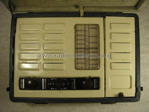
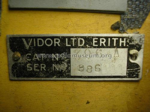
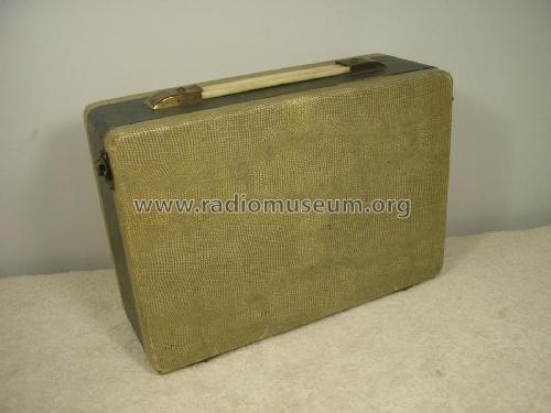
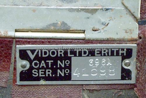
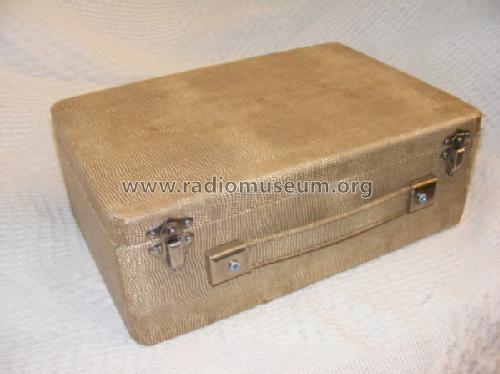
Attache CN396A
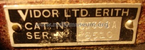
Vidor Ltd.; Erith (Kent)
- Country
- Great Britain (UK)
- Manufacturer / Brand
- Vidor Ltd.; Erith (Kent)
- Year
- 1950
- Category
- Broadcast Receiver - or past WW2 Tuner
- Radiomuseum.org ID
- 74149

Ebay Nr. 260000388433 bearbeitet
Ebay Nr. 260000388433 bearbeitet
Ebay Nr. 260000388433 bearbeitet
Ebay Nr. 260000388433 bearbeitet
Ebay Nr. 260000388433 bearbeitet

Ebay Nr. 260000388433 bearbeitet
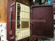
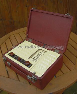
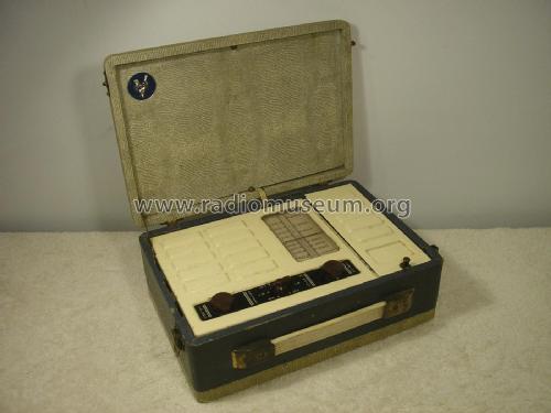
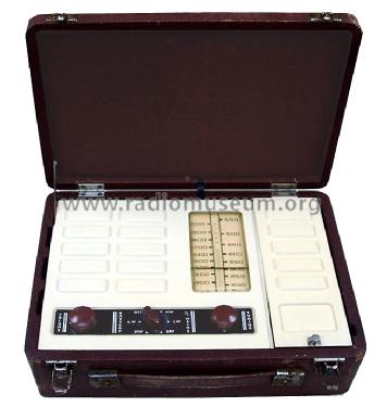
After restoration
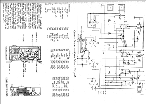
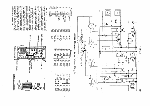
Click on the schematic thumbnail to request the schematic as a free document.
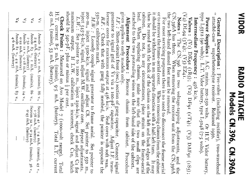
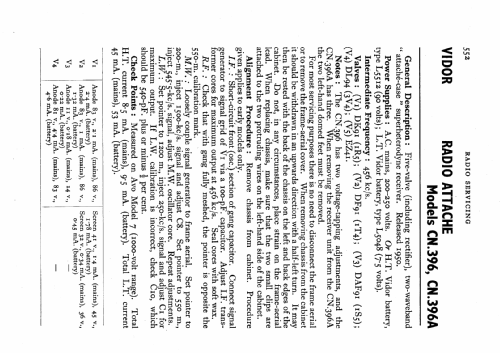
- Number of Tubes
- 5
- Main principle
- Superheterodyne (common); ZF/IF 456 kHz; 1 AF stage(s)
- Tuned circuits
- 6 AM circuit(s)
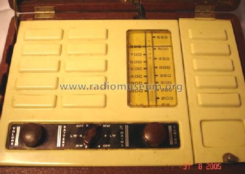
- Wave bands
- Broadcast (MW) and Long Wave.
- Power type and voltage
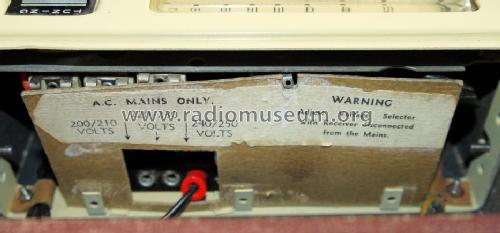
- Line / Batteries (any type) / 200-250 / 7.5 & 90 Volt
- Loudspeaker
- Permanent Magnet Dynamic (PDyn) Loudspeaker (moving coil) / Ø 11 cm = 4.3 inch
- Power out
- 2 W (unknown quality)
- Material
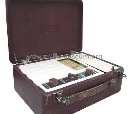
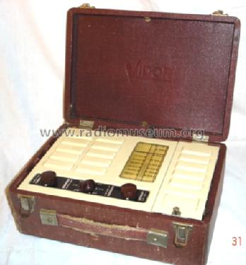
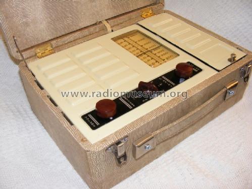
- Leather / canvas / plastic - over other material
- from Radiomuseum.org
- Model: Attache CN396A - Vidor Ltd.; Erith Kent
- Shape
- Portable set > 8 inch (also usable without mains)
- Dimensions (WHD)
- 290 x 200 x 110 mm / 11.4 x 7.9 x 4.3 inch
- Notes
- Three voltage tapping adjustments. Model CN396 has 2 tappings, otherwise almost identical.
- Price in first year of sale
- 215.00 Nlg
- Circuit diagram reference
- Radio and TV Servicing books (R&TVS) book
- Literature/Schematics (1)
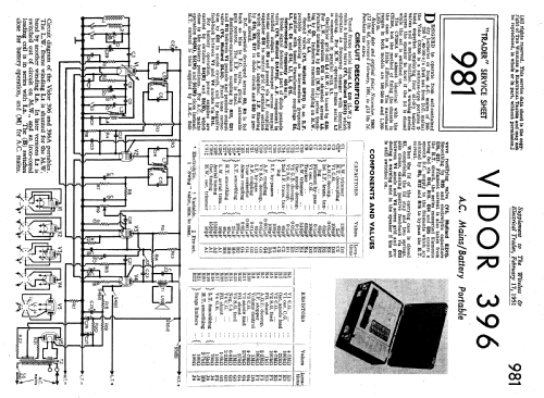
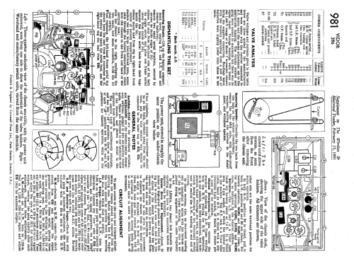
- -- Schematic (Trader Sheet 981.)
- Author
- Model page created by Karel De Reus †. See "Data change" for further contributors.
- Other Models
-
Here you find 146 models, 77 with images and 75 with schematics for wireless sets etc. In French: TSF for Télégraphie sans fil.
All listed radios etc. from Vidor Ltd.; Erith (Kent)
Collections
The model Attache is part of the collections of the following members.
Forum contributions about this model: Vidor Ltd.; Erith: Attache CN396A
Threads: 2 | Posts: 3
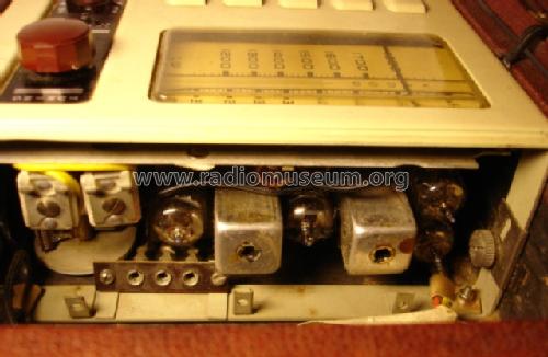
Mine has 1R5 (RCA USA), 1T4 (RCA USA), 1S5 (Emerson USA) and DL94(Mullard) rather than the DK91, DF91, DAF91 and DL94.
Are the US tubes imports used as replacements after sale, or Factory alternate sources?
The maker label is very clear on the 1R5 but the actual "1R5" is missing. I notice on the 1T4 that the "1T4" is different much fainter ink than the "RCA made in USA".
Michael Watterson, 05.Dec.11
This only applies to the 396A, not the 396.
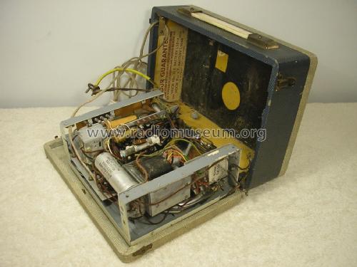
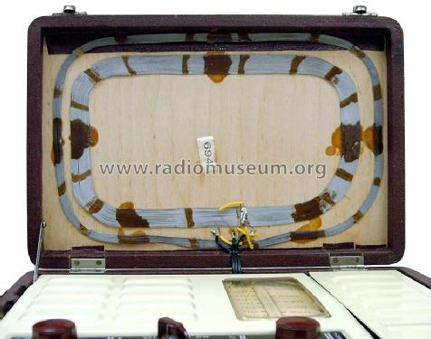
First take off inner cover on lid hiding loop aerial and unsolder 3 wires, identifying them for reconnection. (three colours of nail varnish on wire and terminals?)
There are FOUR fastenings to remove!
1) Remove 2x thumb nuts visible on frame at edge of battery compartment.
2) Unscrew 2 x metal feet (which are disguised bolts) at opposite side.
3) Push Chassis toward battery space to unhook frame from the two studs at side of battery compartment.
The Chassis will not lift out far:

4) 2 x clip on wires to springs at side. This is the alarm if lid is closed while on.
5) You did disconnect and identify aerial connections?
There is a mix of wire types:
1) "cab tyre rubber" wire like from 1920s & 1930s style. It may have perished.
2) "plastic". Should be OK
3) Sleeves like fibre glass, but smooth and coloured (I don't know what it is). Should be OK.
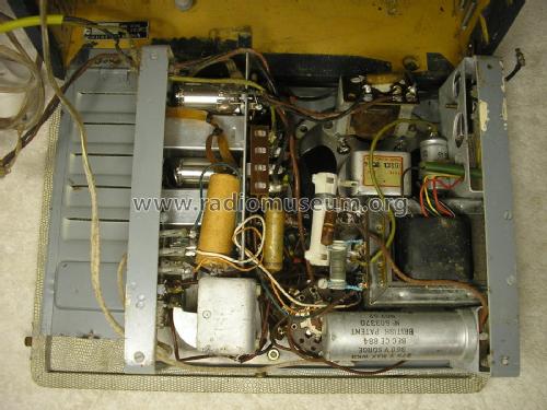
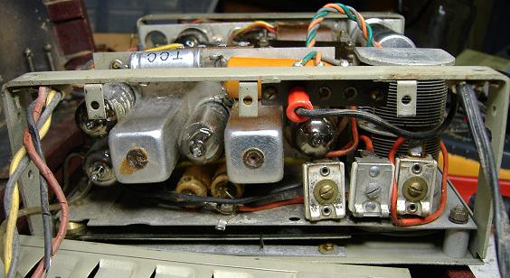
Further removal of the two sub chassis is needed usually.
To clean/repair speaker, replace wires or capacitors.
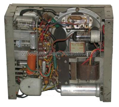
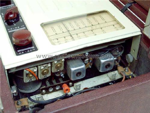
To remove Mains chassis
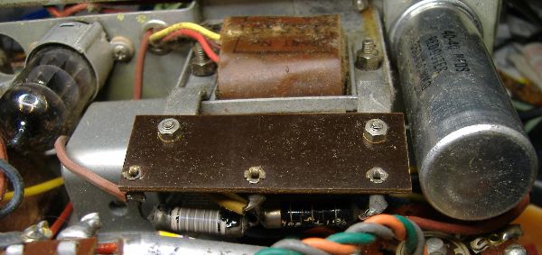
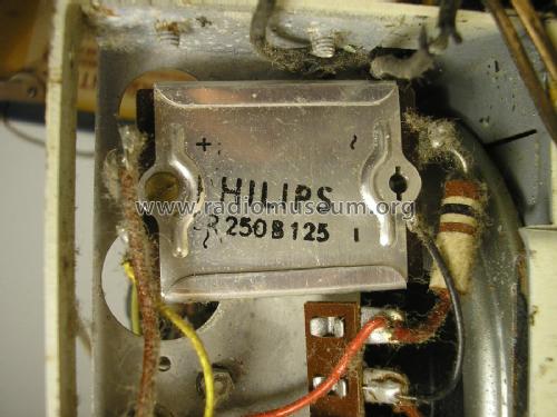
1) note colours of the three mains taps and cut/unsolder at "tap" connector
2) cut/remove wire from two wire-wound resistors just above transformer at power/band switch noting location. (LT?)
3) unscrew mains cable clamp
4) cut / remove wire from transformer to switch (blue on mine), note/mark location. (Mains in)
5) cut/remove wire at base of 40/40uF cap and 2k7 resistor (HT to set), leaving other end of it on the switch).
6) unscrew 2 screws at 2 x sides and two smaller screws at base of transformer at middle of end chassis bar. (6 total).
7) slide PSU out side end of chassis.
Note that the 7.5V +LT is "dropped down" from the "90V" HT line on Mains operation. 50ma Series chain with 1.2K & 700 Ohms in series. Replacement of the Dx91 series + DL94 with Dx96 series would need an increased series resistor.
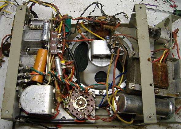
Remove Radio Chassis next
(note Green/Orange/grey wires, mains taps, need removed first)
1) undo 3 x chassis nuts.
2) mark and note wires to volume control and remove (or unbolt control)
3) Mark and note wires to o/p transformer and remove.
4) Lift chassis off.

The loudspeaker can now be unbolted and/or dial plastic cleaned.

Don't lose the 3 x spacers!
(You can see one spot welded pillar came off, it can be epoxied on)
The loudspeaker may need some attention!

If the plastic dial cover is very distorted it can be straightend after warming gently with a desk lamp. But clean completely first. Gently heating with a heat gun or grill and pressing on a hard surface can remove scratches or distortion, but it would be easy to distort it more.
Michael Watterson, 27.Nov.11