Oriole 5 4 tubes
W-K (W.K.) Electric Co. (Winther-Kenosha); Kenosha, WI
- Country
- United States of America (USA)
- Manufacturer / Brand
- W-K (W.K.) Electric Co. (Winther-Kenosha); Kenosha, WI
- Year
- 1925

- Category
- Broadcast Receiver - or past WW2 Tuner
- Radiomuseum.org ID
- 243909
-
- Brand: Oriole


Click on the schematic thumbnail to request the schematic as a free document.
- Number of Tubes
- 4
- Main principle
- TRF with regeneration
- Tuned circuits
- 2 AM circuit(s)
- Wave bands
- Broadcast only (MW).
- Power type and voltage
- Storage and/or dry batteries
- Loudspeaker
- - This model requires external speaker(s).
- Material
- Wooden case
- from Radiomuseum.org
- Model: Oriole 5 [4 tubes] - W-K W.K. Electric Co. Winther-
- Shape
- Tablemodel, Box - most often with Lid (NOT slant panel).
- Notes
-
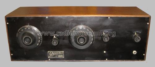
Two dials (primary tuning control knobs) - really existing or mentioned? EE: Despite naming 1924 as first year for Oriole 5 we change it to 1925 since the tube UX201A was according to Tyne, page 315 only available since August 1925 or later. If the model was first fitted with UV-tubes, then the date 1924 would be OK, since the UV201A was available since December 1922. In this case we would have to show the original tube line up and explain things - or create a second model and link them together - with the two different tube line ups.
- External source of data
- Ernst Erb
- Source of data
- Radio Collector`s Guide 1921-1932
- Author
- Model page created by Konrad Birkner † 12.08.2014. See "Data change" for further contributors.
- Other Models
-
Here you find 23 models, 12 with images and 4 with schematics for wireless sets etc. In French: TSF for Télégraphie sans fil.
All listed radios etc. from W-K (W.K.) Electric Co. (Winther-Kenosha); Kenosha, WI
Forum contributions about this model: W-K W.K. Electric Co: Oriole 5
Threads: 1 | Posts: 1
Fellow Radiophiles:
Robert Lozier is a prominent radio collector and amateur historian in the United States. You can find his web page by searching for his radio amateur call kd4hsh.
Robert has restored several Winther-Kenosha radios and has collected signficant information along the way about this company. Robert wrote the following article about some of his findings and presented it at the 2018 AWA Conference in Henrietta, NY. Robert has kindly consented to have it published here. Thank you Robert!
First product by the W-K Electric Co.
Kenosha, Wisconsin
Circa 1924-25.
Oriole - Model 5

From the collection of: Robert Lozier, Kd4hsh[A*T]carolina.rr.com – 704-458-1076
Four tube radio with one stage of TRF (with regeneration), Detector and Two audio stages. For long wire or loop antenna. In 1924 the young designer, Mark Kindt, got publicity for his ‘revolutionary’ design and ideas that you can read here. However, the public record of his radio building activities goes quite cold right afterwards; even though he was known to be a principal in W-K and successor companies. This first product did not use the unique Trinum circuit incorporating their first use of cathode follower RF amplifier stages.
Introduction
 In 2014 and 2017 I read articles in the MAARC monthly publication, Radio Age about unique radios manufactured by W-K Electric Co., Kenosha, Wicsconsin. On a whim, after reading the 2017 article about their Warwick 71 model, I decided to make an e-Bay search. Within a couple of days one pops up with a Buy It Now of (I think) $90 and about $45 for shipping. Even though I have been trolling e-Bay for 20 years, this was the FIRST full size vintage radio I had ever purchased on the site! It came very well packed and I began my usual routine of documenting what I had received by making several dozen photographs and then searching the Web for any references to the components used to build the set. I was happy to find that the Wisconsin Antique Radio Club has a very good Web site and has many years of their monthly news letter available for download. They have articles on the W-K Electric Co. and links to other sites. In my research on Oriole I came across the Oriole registered trade mark application. This document showed the name of Mark Kindt as being an officer of the company. Searches on his name eventually turned up a newspaper article from January 1924. It contains a photograph of Mark holding a radio chassis and there is another radio on view below him. Versions of this article were syndicated and appear in at least five other newspapers in June of 1924.

A friend, Stephen Brown, was aware of my continuing interest in Oriole and alerted me to an e-Bay listing in May of 2018. It was for this Oriole Model 5. The hard rubber front panel appeared to be in terrible condition but I decided to bid on the radio because it appeared to be very similar to the one Mark is holding in the article photograph! This was only the second radio I have purchased from eBay in 20 years!
Sure enough there is unmistakable evidence that the Model 5 was the first commercial product after the formation of W-K Electric Co. This is confirmed by listings in the late Greg Hunolt’s Battery Set Compendium and surviving advertisements in vintage publications.
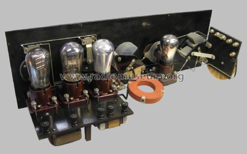
Model 5 Description The circuit has one stage of Tuned RF amplification (with regeneration) followed by a detector and two stages of transformer coupled audio amplification.
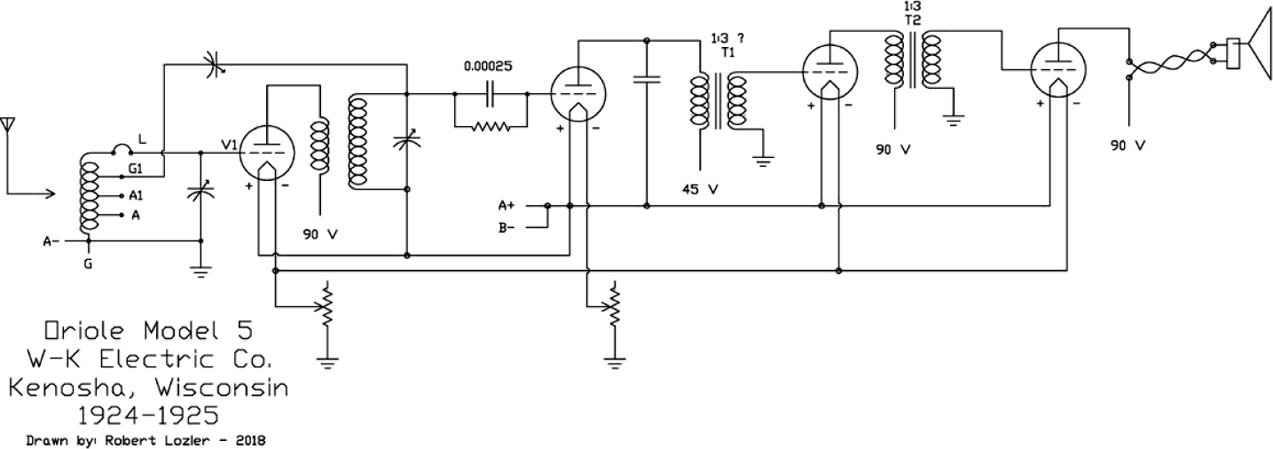
Note that the detector is not wired for regeneration. The basket weave input coil is wired to accept long and short antennas and has a jumper scheme for connection of a loop antenna. The RF transformer between the TRF stage and detector is contained in a curious doughnut shaped enclosure made of heavy weight red fiber paper stock. It is made such that the enclosure would have to be heavily damaged to open for inspection of the winding. I have not yet made attempts to measure the turns ratio of this RF transformer.
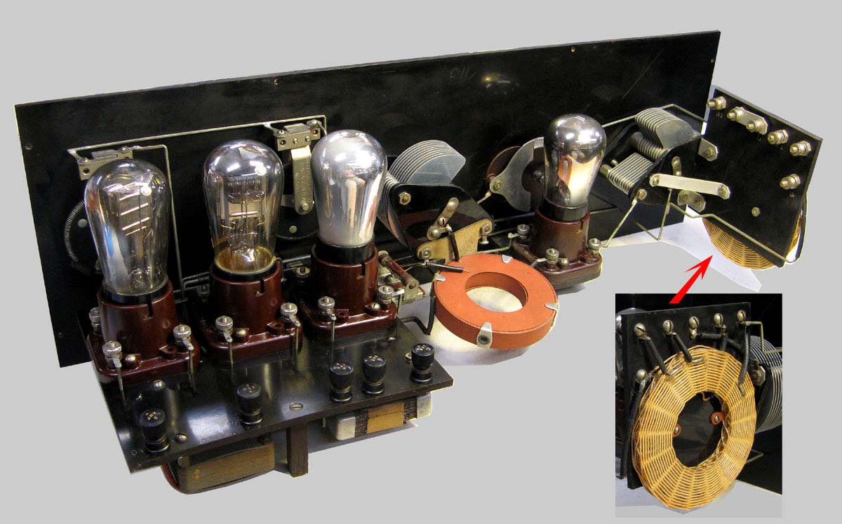

The audio transformer between the detector and first audio tube is of somewhat curious construction. There can be no doubt that this is indeed the original part for the radio. Unfortunately both windings were open circuit… One winding, the secondary, had been chewed on by a mouse or insect but I was able to repair the wire break and make a resistance measurement of 3.2k Ohms. The primary however remains open circuit. Even attempts to bridge the open with a 500 Volt charged capacitor did not cause current to flow. My inspection of the winding layers from the side suggest that the turns ratio must be about 1:3…. Certainly not 1:5 as seen on some contemporary radios between the detector and first audio tube.

I have never seen an audio transformer with deep-drawn aluminum cups as the support method. Nor have I seen an audio transformer with ‘U’ laminations with so many gaps in the magnetic path of each stack layer. The other transformer appears to be much better made and again there can be no question that it is original to the build.
 Since the first audio was open circuit, I decided to install a Solid State Transformer substitute I call SST1D. The circuit was designed by Jay Kinnard of Austin, TX and I decided to implement the design in surface mount components in order to make the smallest practical part for concealment in many radios. (0.7” x 0.85”) My goal is to make a part so small that it does not require the removal of the original transformer; it is simply wired in parallel. In this Oriole, the SST1D is very difficult to spot on the underside of the chassis. But it works very well indeed…

Jay reports that this version of the circuit produces just about the same levels of distortion, about 6%, of the original transformer coupled amplifier. He determined that with the addition of two parts, he could reduce the distortion to 2% but I told him that I would NOT want the radio to perform ‘better than new’. My goal is to have the radio perform as nearly equivalent to its original design as possible.
The Battery Set Compendium lists also for 1924 a Model 6 receiver then in 1925, an Oriole Model 60 and an Oriole Model 7. The advertising verbiage for the Model 7 makes reference to a “new circuit” that we can infer is the “Trinum” circuit. There are existing examples of a Model 7-B confirming the use of the cathode follower RF amplifier and the Trinum circuit name. There exists a copy of a letter dated January 3rd, 1998 from British historian and collector, Pat Leggatt , to Alan Douglas. He reports that a Model 7 wound-up in the UK and he was able to make a sketch of the schematic that clearly shows the cathode follower RF amplifier hook-up. Therefore I can presume the Model 7 would be the first American made radio to make use of cathode follower RF amplifier stages. At present there are no known examples of the Model 6, 60 or the whereabouts of the late Pat Leggatt’s Model 7; while there is at least one example of the 7-B.
Back to the 1924 newspaper articles….
The first article appears in the Madison, Wisconsin Capital Times for January 2nd. 1924. In June of 1924 rewrites of the article appear in at least six other newspapers. Battle Creek Enquirer, Eau Claire Leader, Evening News, The Tennessean, The Times and Wausau Daily Herald all with the same picture used in the original article. It is fun to compare the rewrites. Some of the articles imply that Mark Kindt and Anthony Winther were ‘hams’ but I have not been able to find either name listed in call books of the times.
Restoration
Other than the horrible front panel, the radio only required some careful cleaning. My preferred cleaner for hard rubber or Bakelite is regular Go-Jo or Goop waterless hand cleaner. I never use water for removal of the residual, only dry cotton towels or gauze pads.
To address the front panel problems it was necessary to strip all components from the panel. It appears someone had attempted to clean this Radion brand hard rubber panel using something very caustic. The net result was an ash tan rough surface.
 I determined that the panel would need to be sanded level; the only problem was that I had no indication of how deep the discoloration had penetrated. Before I could proceed, I had to deal with the shallow arcs & arrows engraved in the panel. Fortunately it was not difficult to deepen these arcs using a small machinist compass.
I used a 220 grit sanding pad lubricated with low VOC mineral spirits (white spirits). I spent more than two solid hours of hand sanding until I had a smooth surface with most of the surface returned to a black hue. This was followed by long lateral strokes using #0000 steel wool also lubricated with the spirits to produce a satin sheen. Cotton pads were used to remove the residual mineral spirits.
In an attempt to return the whole surface to a uniform black, I used a cotton pad to apply alcohol based Black aniline wood dye. After drying, you have uniform color but it has a definite, unacceptable, metallic magenta hue. Many years ago I had discovered TR3 ‘deep cleaning’ auto wax. Consumer Reports had always given it low marks because it was deemed too abrasive. It appears that this product has a relatively large percentage of very fine rotten stone in it that, when wet, with water or wax appears black. The net result is that any microscopic residual material does not show up as a cloudy white coloration. I understand that there are colored auto waxes today such as Meguiar's G6207 Black Wax Paste that may produce the same effect.
As it turns out, rubbing the TR3 over the dried aniline Black dye removed the magenta hue and produced a hard waxed surface that should remain stable for some time.
As mentioned above, the first audio transformer is open circuit.
This turned out to be an ideal opportunity to hide a SST1D transformer substitution circuit so that the radio can be operated.
The board is wafer thin and can therefore be wrapped in a slip of black paper. There simply is no way to repair or replace this unique audio; so much better for history sake to keep it in place.
There is only the necessity to disconnect the windings from the buss bar wiring of the radio. This is accomplished by reflow soldering tiny (1/8”x 5/16”) chips of double-side printed circuit material to the side of the buss wire. At the same point, the tiny wires from the SST1D board are connected. These board wires are covered with tiny black braided cotton sleeving that can be very difficult to spot. The other side of the PCB chip is simply a little insulated island to which the original transformer wire can be tacked. This preserves the original routing of wiring. The justification for actually disconnecting the transformer wire is that a particular wire to the transformer may not be open on that end of the winding and therefore will represent some unknown amount of stray capacity and inductance into the circuit.
When you have finished the wiring change, clean the solder joints and then give them a light coating of flat gray acrylic paint. The dull joint looks very much like old oxidized solder so is very effective in not drawing attention to your work.
This radio cabinet is coated in shellac that has “alligatored” over time. After cleaning with Go-Jo, I noted that the finish was actually quite free of embedded soil. It would be an easy task to strip the finish with alcohol but in this case I have decided to leave as is.
 Inside the cabinet is a paper label: “ORIOLE CABINET built by Kenosha Pattern Works, Kenosha, Wis. Number______” The hinged lid is stamped along its front edge with the number 9.
There is a matching number 9 along the inside of the top board of the cabinet. On the back side of the Radion hard rubber panel is deliberately scratched “C11” with a sharp object. This suggests to me that this radio was being made in very small batches. There is mention of their working in a “shed” before moving to a building on the “Barnett property, attached to a coffin shop and fishing shanty”. Research by WARCI member Gil Benn tracked the location to now be designated 443-50th Street.
This Model 5 apparently did not make it into the marketplace until after the June 1924 syndicated newspaper articles and was superseded by the “New” 5 Tube Oriole as advertised in a W-K Electric ad, Radio Industry, June 1925. This new model was the first to make use of the cathode follower RF amplifier circuit(s).
Robert Lozier, kd4hsh
Attachments
- Oriole 5 Schematic (47 KB)
- chassis back (128 KB)
Joe Sousa, 11.Jan.19