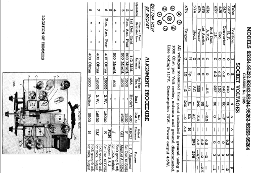
9S262 9-S-262 Ch=5905
Zenith Radio Corp.; Chicago, IL
- Country
- United States of America (USA)
- Manufacturer / Brand
- Zenith Radio Corp.; Chicago, IL
- Year
- 1937
- Category
- Broadcast Receiver - or past WW2 Tuner
- Radiomuseum.org ID
- 68145
-
- alternative name: Chicago Radio Lab


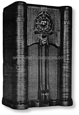
Copy gen. von John Goller Radio Attic
With courtesy by Craig Delf

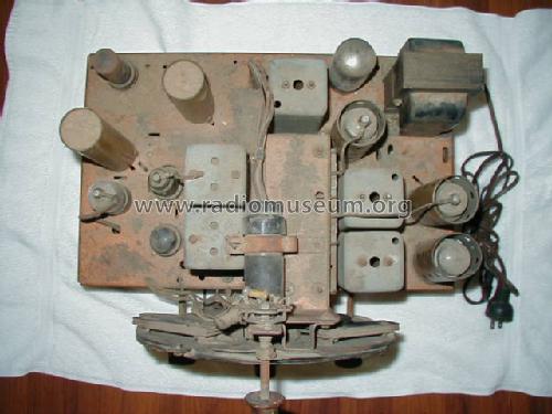
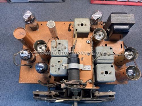
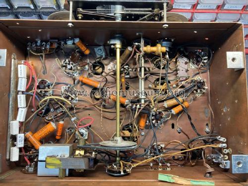
With courtesy by Craig Delf back-view

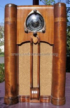
with courtesy by Craig Delf dial-view


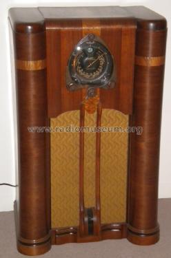
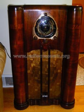
Refinished cabint
Click on the schematic thumbnail to request the schematic as a free document.
- Number of Tubes
- 9
- Main principle
- Superhet with RF-stage; ZF/IF 456 kHz
- Wave bands
- Broadcast, Short Wave(s) and Police.
- Power type and voltage
- Alternating Current supply (AC) / 115 Volt
- Loudspeaker
- Electro Magnetic Dynamic LS (moving-coil with field excitation coil) / Ø 12 inch = 30.5 cm
- Power out
- 4.5 W (unknown quality)
- Material
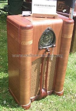
- Wooden case
- from Radiomuseum.org
- Model: 9S262 9-S-262 Ch=5905 - Zenith Radio Corp.; Chicago,
- Shape
- Console with any shape - in general
- Dimensions (WHD)
- 26.9 x 42 x 16.8 inch / 683 x 1067 x 427 mm
- Price in first year of sale
- 100.00 $
- External source of data
- Ernst Erb
- Source of data
- The Radio Collector's Directory and Price Guide 1921 - 1965
- Circuit diagram reference
- Rider's Perpetual, Volume 8 = 1937 and before
- Mentioned in
- Collector's Guide to Antique Radios 4. Edition
- Literature/Schematics (1)
- Zenith Radio The Glory Years 1936-1945
- Literature/Schematics (2)
- Pre-War Consoles
- Other Models
-
Here you find 4491 models, 4096 with images and 3595 with schematics for wireless sets etc. In French: TSF for Télégraphie sans fil.
All listed radios etc. from Zenith Radio Corp.; Chicago, IL
Collections
The model 9S262 is part of the collections of the following members.
Forum contributions about this model: Zenith Radio Corp.;: 9S262 9-S-262 Ch=5905
Threads: 1 | Posts: 15
Is some one willing to assist me in troubleshooting my Zeinth 9s262, Shutter Dial. My background kind of goes like: About 1963, I took tube radio repair in vocational high school just as transistors came on the scene and the demand for warm bodies for Viet-Nam draft soared. Since I had a rudimentary understanding of radio electronics, the decision was made to use those skillls in selecting my military career path which was of course engine mechanics. That never detered me from my path of radio collecting. Over the last 40 years I have maintained a collection which now numbers 95-100 radios and spring wound phonographs. I decided I would collect while I had the opportunity and as I neared retirement I would begin what I like to call "polishing" my collection. Which, after all of that, brings me to my point. Man, have I ever forgotten what I thought I knew about radio servicing. Most of the time, I'm lucky and find a bad tube or a melted capicator but not this time. I bought two Zenith consoles at a real good price, both in 7 or 8 out of 10 in quality. The 10s470 is great, looks to have been serviced by a Zenith dealer....all Zenith components plays and sounds new. The other is a 9s262 Shutter Dial. Initial tube checks showed the 6F6 Audio tube with extremely low emmision. I replace the 6F6 and now it overheats and will leave a blister if you touch it. Audio is very low no matter where the volume is....selectivity is marginal. A signal at the volume control indicates that the amp is working. If speaker is disconnected the tube won't overheat but will overheat on a known good speaker with the same load. The absolute worst is that someone has been in the set changing capacitors and I'm not sure where to start. Any guidence will be sincerely appreciated
Joe Rose, 25.Nov.08