
12BA7

|
|
|||||||||||||||||||||||||||||||||||||


|
Hits: 13109 Replies: 4
12BA7 to 12BE6 or 12SA7
|
|||||||||||||||||||||||||||||||
|
Joe Sousa
02.Mar.10 |
1
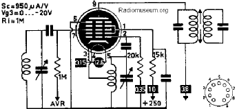
Fellow Radiophiles, One of the things I enjoy when repairing my tube radios, is getting them to perform as well as they can. One way to improve the RF gain and AGC action of sets that use the 12BE6 or 12SA7 pentgrid frequency converters is to upgrade them with a 12BA7. I first heard about this trick at the web page for WA2ISE by Robert Casey. Bob explores may ways to "hot rod" the performance of American AC-DC radios. The specified conversion transconductance for these three pentagrid converters is as follows: 12BE6 gc=475uS 12SA7 gc=450uS 12BA7 gc=950uS The 12BA7 gives twice the conversion transconductance of the other tubes. Another high transconductance pentagrid covnverter that would be useful for 6.3V filaments is the octal 6SB7Y, with gc=950uS, and the same pinout as the 6SA7. The conversion diagrams show a fairly straight-forward method of wiring up socket adapters.
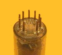
The 7pin plug for the 12BA7-12BE6 socket adapter is hard to find. I tried reusing the glass button from a dead 7 pin tube, but the tube metal would not solder. The octal plug is very easy to reclaim from a dead octal tube. The 9 pin socket of the 12BA7 even fits very nicely inside bakelite plug. Click on these thumbnails for wiring detail:
I built these two adapters to try on two AC/DC radios that could use a bit more gain. One is the 5 tube Teletone 990 with a 12BE6 but only one IF transformer.
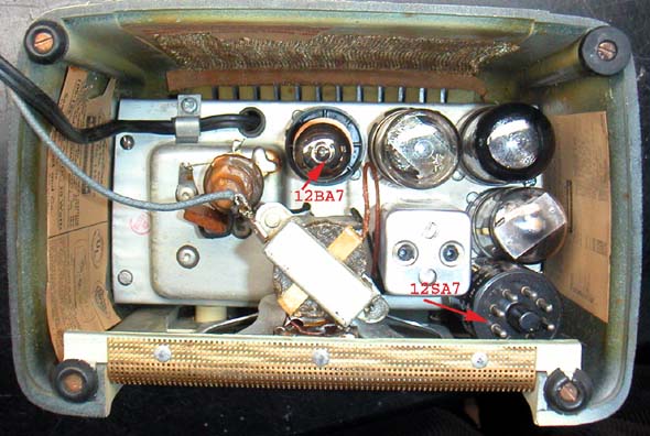
and the other the 4 tube Silvertone 8000 with a 12SA7. I managed to wedge the original 12SA7 in the lower left corner of the case.
One thing to keep in mind is that the capacitance of the new 12BA7+adapater is different from the capacitance of the original tubes. My method to deal with this difference in capacitance is a short procedure: 1-Tune radio with original Pentagrid converter (12BE6 or 12SA7) to a station at the high end of the dial, for maximum signal. You can do this by ear, or with a high impedance (>10Meg) DC voltage measurement of the AVC line. 2-Replace the original Pentagrid conver with the 12BA7 without touching the tuning dial. 4-Let the radio warm up with the 12BA7. you will notice that the station may actually be weaker or gone. This is due to a shift in Local Oscillator frequency with the 12BA7+adapter stray capacitance. 5-Still without touching the dial, adjust the trim capacitor for the local oscillator to bring the station back in. You should noticed substantially stronger volume than before, or a more negative AVC voltage. I made a casual measurement of the performance improvement with the Teletone 990 with a DC measurement of the AGC line: No signal AVC=-0.8V 12BE6 AVC=-1.5V 12BA7 AVC=-2.5V This is nearly a factor of 4 improvement in output signal. Some of this may be simply a result of improved detector efficiency, when running with a stronger signal. The improvement for both radios was also quite obvious to my ears. A cursory look through European Hexode-Triode frequency converters shows a range of conversion transconductanc between 400uS and 750uS. Perhaps someone knows of a "hot" Hexode-Triode. Regards, -Joe
|
||||||||||||||||||||||||||||||
|
Jose Vigil
02.Mar.10 |
2
Hello Joe. Very interesting approach. I will try it when I have a 12BA7. There is another way to improve sensitivity on AC/DC American sets. It was used on the Hallicrafters Echophone 102. They used a 12SG7 at the IF amp. Instead of the 12SK7. I tried it in a The socket connections are not exactly the same. The cathode is tied to the suppressor grid. They are pins 3 and 5 that in some sets are short circuited.. Besides this they are direct replacement. Transconductance for the 12SG7 is 4100 umhos. For the 12SK7 is 2350 umhos at the same conditions. Almost twice. Best regards, Jose Vigil
|
||||||||||||||||||||||||||||||
|
Joe Sousa
03.Mar.10 |
3
Hello Jose, Thanks for the reference to the 12SG7 pentode. This morning, on the way to work, I stopped off at Malco Electronics in Lawrence Massachusetts USA, and picked up their last two 12SG7 pentodes. ( I like to brag that I still have an electronics shop in town that has been in business since tubes were their highest sellling item!) I decided to try the 12SG7 in the IF stage of my Delco R-1233. I was a bit surprised with the results. It appears that the gm advantage of the 12SG7 over the 12SK7 is valid only at the lowest control grid bias level. The difference in performance between the two tubes was not as obvious as it was with 12BA7 vs 12SA7 pentagrid mixers mentioned above, despite a two-to-one ratio in transconductances in the pentodes. I compared tube gain between the two pentodes by forcing the AVC voltage at the AVC filter cap with an external supply, while retuning the IF stage for maximum signal for each tube, and measuring the signal voltage at the top of the volume control. The signal was from WBZ AM-1030kHz in Boston Massachusetts USA, about 30 miles from my home.
I performed another test where I tuned in three stations and measured the resulting AVC voltage as measured at the top of the 500k volume control, but with the AVC in normal operation. I compared reception for three different stations:
The grid self bias potential at the AVC cap without any signal was -0.5V for both tubes. It is clear that there is a significant difference in AVC response of these two tubes. The GE data sheet for the 12SG7 describes the tube as a Semi-Remote cutoff type. This implies a sharper AGC action at the expense of tolerating smaller maximum signals at a given distortion. The AVC compression is tighter with the 12SG7, and the low signal gain is twice, as promised by the higher transconductance. Perhaps the 12SG7 would work best as an RF front end, running with a delayed AVC voltage with respect to the following stages. Another good use for the 12SG7 may be in small TRF sets with 3 or 4 tubes, to replace the 12SK7 at the first stage. Regards, -Joe
|
||||||||||||||||||||||||||||||
|
Jose Vigil
03.Mar.10 |
4
Hi Joe. Thanks for the information of the measured voltages. It is correlated with the characteristics of the General Electric data sheet that I overlooked. For about the same plate and screen voltages, the cut off grid voltage is almost three times larger on the 12SK7. 12SG7 cut off voltage for 100 V at both plate and screen = -11.5 V 12SK7 in the same conditions -35V You are right on at the applications In the case of the Hallicrafters, the cutting edge of this set was to be a very good short wave receiver at very low cost. It has an accurate calibrated dial and separate spread control. Also graduated. It is a charm to tune. I will take a close up photo of the dial to upload at the model page. About the use in a medium wave set such as the Emerson 511. It has a clear advantage for weak signals. Perhaps with nearby stations the crossover distortion is a problem. Best regards, Jose |
||||||||||||||||||||||||||||||
|
Joe Sousa
05.Mar.10 |
5
Hi Jose, The contrast in cutoff voltages you report illustrates clearly the different AGC action for these two tubes. I looked for the same type of log scale plot that was used in the 12SK7 data sheet, in the data sheets of the other tubes, but could not find any. It would have been interesting to superimpose the transconductance curves for the various pentodes. Other candidate pentodes with a compatible octal pinout and remote cutoff might be: 12SH7 gm=4.9mS 12AB7 gm=5mS 12SD7 gm=3.6mS One of the very useful features at RMORG is the listing of radios each tube type is used. I started on the 12SG7 tube page and followed some of the radio links. The 12SG7 was often used as the RF preamp in some designs: Radio Wire 617 618 from 1952 Regal 7162 from 1949 RCA mi-13174-3 from 1949 RCA 26X4 from 1941 and as the IF amplifier in radios without an RF preamp: Hallicrafters AM/SW ssb S38D from 1954 Temple AM/FM H727 from 1953 Hoffman 205 from 1951 One interesting surprise in this survey was to find the 6SB7Y pentagrid converter which has 1mS of conversion transconductance, used in the Temple AM/FM H727. The surprise is that this radio has a 150mA series heater string, but the 6SB7Y at it's front end requires 6.3V at 300mA.
The clever trick to supply the additional current for the 6SB7Y heater is to wire it's heater in series with the other heaters, as well as in series with the rectifier path. In other words, all the current into the radio must pass through the 6SB7Y heater. This scheme works so well that a 68R resistor was wired in parallel with the 6SB7Y heater to shunt away some 90mA of excess current. The total current draw for this radio is 390mA rms and 300mA of this current passes through the 6SB7Y heater. Some of the extra current in this radio comes from the 35L6 pentode pair used in parallel at the output. Regards, -Joe
|
||||||||||||||||||||||||||||||


End of forum contributions about this tube
| Data Compliance | More Information |