
1Ж24Б1j24b

|
|
|||||||||||||||||||||||||||||||||


|
Hits: 6287 Replies: 1
Logic Family built around 1j24b
|
|
|
Joe Sousa
12.Sep.11 |
1
Fellow Radiophiles: The notion of building logic gates with filamentary tubes has intrigued me for a long time. Nearly all Tube based digital computers from the 1950's were built with indirectly heated cathode tubes. Emilio Ciardiello has uncovered evidence of the existence of digital computers with filamentary tubes for low power applications in Avionics. He also found that Raytheon attempted to market some of it's subminiature filamentary tubes for computer use. The Russian rod tube construction yields very low screen current, typically under 10% of the plate current. This good current gain>10, from screen to plate, made me think of the possibility of building a logic family with tubes that are completely direct coupled from the plate outputs to the screen grid inputs of the next gate. The only additional component is the plate pull-up load resistor. Topologically, this recalls NMOS logic, where the singled ended drain load drives the gate of the next logic element. Perhaps a shaddow grid scheme could have been done with conventionally gridded tubes to achieve a high current gain from G2 to P. In it's simplest form, a logic family can be built from a single inverting gate with two or more inputs. But, very often, more complex elements like flipflops are customized, as in the use of transmission gates in CMOS flipflops. My approach here is to build a single inverting gate with two or more inputs with a robust Fan-in and Fan-out characteristic.
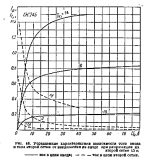
The relatively high supply voltage of +90V was paired with the relatively high plate load resistance of 100k, so that 1mA can be pulled by either tube with a screen grid drive of only 50V. The combination of high supply voltage and high load resistance achieve high gain. The high level voltage without a load is the full supply voltage. When a screen load is present, the logic high is 62V, 55V, 50V when loaded with 1, 2, 3 screen loads respectively. These levels represent the de-facto high logic level. The low logic level is set by the plate saturation between 3V and 5V. The input resistance of each screen grid exhibits a limiting characteristic that results from the plate saturation at low voltages, but is also >100k when driven with less than a logic high and the plate is not saturated. The following three curve tracings of the 1j24b show the essential characteristics that are useful to choose bias levels and load resistance for the NOR gate.
The first plot shows plate current as a function of plate voltage and is stepped every 20V at the screen grid G2 up to +100V for the top curve. This gives the essential transconductance from G2 to P around 60uS. The 100k Load line to the 100V supply intersects a low saturated voltage around +5V when G2 is about 45V.
This plot shows screen grid G2 current as a function of it's voltage, but stepped in 10V steps of plate voltage, up to 50V at the plate. Above 50V at the plate there is negligible effect on screen current. Note how the screen current goes up greatly when the plate drops below the 10V step. Below +10V at the plate, the current is reflected back to the screen grid G2. Scale: G2=50uA/div, 10V/div
This special curve family shows screen grid G2 current as function of it's voltage for various load resistances from the plate to a +100V power supply. The resistance values on the plot are all plate load resistance values to the +100V supply.
Note the very sharp limiting characteristic seen for plate resistances below 26k. This limiting characteristic is a manifestation of the plate saturation at low plate voltages. The saturated voltage at the plate, is thus reflected at the screen grid G2.
It is this reflected voltage at G2 that establishes the logic high level of any loaded gate between +50V and +62V, as noted above.
Scale: G2=50uA/div, 10V/div
As much as the circuit topology is trivial, it is made this simple because of the very special electron-optic beam properties of these tubes that yield unusually low screen current, which is to say, unusually high screen grid G2 current gain to the plate. The bias levels at G3 and G1 are very important to attain the highest gain. The current into the suppressor grid G3 at +5V is a few tens of uA.
For example, the optimal bias level for G1 is 0V. Increasing G1 to the high side of the filament voltage at 1.3V, increases plate current perhaps 30%, but dramatically increases screen grid G2 current about 4 fold, due to the defocusing effect that the elevated G1 voltage has on the beam. It is clearly not worth boosting plate current 30%, while loosing most of the screen grid G2 current gain. Thus, the control grid G1 bias remains at 0V. The optimal bias level for G3 was found empirically to be +5V because it boosts screen grid current gain to a maximum, while lowering plate saturation voltage to about 4V. The following curve traces illustrate this in detail.
Scale for 2nd and 3rd plots: G2=50uA/div, 10V/div The first plot shows the increased plate saturation to +10V at the far left of the plot, when the suppressor grid G3 is biased at 0V, as opposed to +5V when the suppressor grid G3 is biased at +5V shown above. The second plot shows a doubling of screen current when the suppressor grid is biased at 0V, as opposed to +5V shown above. The third plot shows the worst possible bias combination, which is with G3=0V and G1=1.3V. This greatly increases screen currents and wipes out most of the screen current gain.
Wolfgang Holtman created the illustration on the left to show beam flow in a typical rod tube. Note how the rod elements for the two opposing beams are wired together to be driven externally as single elements. It is very plausible that a directly coupled NOR gate could have been made with a single tube simply by bringing out separate connections for the upper G2 pair and the lower G2 pair. This would produce a direct-coupled NOR gate in a single envelope, but at half the current drive level that would be obtained with two tubes in parallel.
The following set of DC voltage measurements establishes Fan-in and Fan-out for the NOR gates. A 100k load drives up to 4 NOR inputs (A1, B1, B2, A3). A and B are inputs and QL are outputs. The number indicates which gate. A1 B1 B2 Q1L=A2 Q2L B+=S=90V G3=5V 100K LOADS VF=1.30V 0 0 0 65.2 3.4 62.5 0 0 3.7 89.2 >unloaded 55.0 55.0 0 2.9 89.2 >unloaded 50.0 50.0 50.0 3.0 3.86 Add A3 load to input A3 Q3L 43.1 43.1 43.1 3.4 8.02 43.1 9.82 Add A4 load to Q2L Q2L=A4 Q4L 43.1 43.1 43.1 3.4 7.98 43.1 9.82 88.6 While driving 4 NOR inputs with a single 100k pull-up, produces valid logic levels. The 9.8V logic lows are almost comming out of saturation. Boosting the supply voltage from 90V to 110V would increase the available pull down current to guaranty that the 100k pull-up could drive four NOR gates to full saturation. This demonstrates a robust Fanout of 4 for 100k pull up to 110V supply. Further Fanout derating to accomodate filament emission decay over time may also be desirable. However, the screen grid G2 current gain is set largely by rod geometry and bias voltages, not by emission. A weakening tube would exhibit higher voltages for the high and low logic levels. Fanout can also be boosted by using higher supply voltages and higher load resistors. This would leave the logic high level at the same value as set by the clamping action of G2, but would increase ouput gain for an even more reliably saturated low level. The following schematic shows a 5 stage ring oscillator to ascertain gate delays. The breadboard construction added 3pF of measured capacitance at each input and output. The oscillation frequency was just under 90kHz, which gives a 2.2us gate delay in the 11uS oscillation period. The 3pF breadboard capacitance account for about 300ns of the 2.2us gate delay.
The following illustrates a simple RS latch made with two NOR gates.
Going FurtherWhile I chose the 1j24b because of it's legendary efficiency, other rod type tubes, like the 1j17b or 1j37b could have been used. The higher current levels of these tubes would have substantially increased speed, about 4 fold. The 1j37b, with it's two control grids, could also be used in a more conventional tube-gate configuration where the inputs are resistively level shifted from the plate to the control grids, and it's screen grid is biased at a fixed level. While this is no longer direct-coupled logic, a single 1j37b embodies a full NAND gate from it's two control grids to the plate. More can be found at the Russian Subminiature Tubes thread. Hopefully, this will inspire our more digitally minded fellow Radiophiles to create some interesting all-tube logic design. The tubes are certainly very inexpensive, going for about $1 each on ebay in small lots of 10. Best regards, -Joe
|
|
Michael Watterson
27.Sep.11 |
2
If we implement a very basic cpu with 5,000 x 1j24b valves (hypothetically) then compared with EF80 or similar the power is reasonable. Filament is about 70W HT about 550W For EF80 filament of 5,000 parts is about 9000W (assuming you run it slightly low) Keep up the good ideas Joe. I have appreciated all the other articles you have done on the sub-miniature Russian rod pentodes. It inspired me to make some radio sets. Next I hope to do VHF/MW/LW/SW portable. Perhaps some of the logic gate ideas could be applied to Stereo Multiplex Decoder though maybe RDS is safer as thought experiment than with 1j24b. However I was planning just a Mono FM/AM set. Discussion of that probably in another thread. Sadly I'm old enough to remember discrete DTL logic boards. I used to buy them in the market for the parts (possibly 2N706 and IN60 diodes). Each small board was maybe two gates. You would easily fit the same functionality of 1j24b in about the same space. Also though "fatter" (the 8mm tube), illustrations of the military sets show rectangle cut out for the tube, thus saving slightly more than 2mm depth assuming 1.6mm PCB and more than 0.4m of soldered wire on track side.
|
 The gate is in the simple wired NOR configuration. It is easily expanded for more inputs by parallelling more tubes.


|
Hits: 8464 Replies: 6
1j24b (1j24b)
|
|
|
Michael Watterson
08.Oct.11 |
1
Also known as 1ZH24b, 1sh24b and properly 1Ж24Б Useful information on these kinds of sub-miniature Rod Pentode tubes (valves): The 1j24b is still (2011) readily available to purchase as New Old Stock (NOS). Some stock at least is as late as 1991 Nützliche Informationen über diese Art von Sub-Miniatur-Rod Pentode Röhren: Die 1j24b ist immer noch (2011) leicht zugänglich zu kaufen (2011) leicht zugänglich wie Neu Alte Aktien Kauf (NOS) |
|
Michael Watterson
12.Oct.11 |
2
Cross-section showing top single filament feed Glass (grey) aproximately 8mm |
|
Michael Watterson
18.Oct.11 |
3
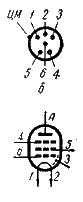
The wiring to a B7G plug for a socket intended for DF96 (DF96 is nominal 24mA @ 1.4V about twice the 1j24b current)
4mm to 6mm of sleeve recommended g1, g2, g3 Some IF amp may need neutralisation or additional screening on around the the whole assembly. If it's a series heater chain a parallel resistor between +f and the -f,g3,s connections is needed. It might be advantageous to put 18 Ohms in series between 1j24b f- and the -f,g3,s plug connection. Works to some extent with no other modification in an Invicta 29 in place of DF96, but if there is no signal or very weak station then turning up the volume results in some feedback, so additional screening and possibly neutralisation, series resistor etc may be needed. [Edit: Actually with a very slight IF transformer adjustment the 1j24b replacement is "stable" without screening and the radio working as well if not better than before ] |
|
Michael Watterson
19.Oct.11 |
4
Bonded Germanium diodes have, I think, been available since 1946. This "plug replacement" to save your DAF96 (or possibly DAF91) uses an 1N60 diode or similar.
Some small adjustment of the IF transformer may be needed. Tested in an Invicta 29. If there is a series filament chain a suitable parallel resistor across pin 1 and 7 is required as the DAF91 is 50mA (RCA 1S5) and the DAF96 is 25mA (both nominal 1.4V). The 1j24b is 11mA to 13mA depending on voltage (0.9V to 1.4V recommended). If desired 18 Ohm could be in series between the 1j24b filament - (wire 2) and pin 1 of the B7G. This will also slightly reduce HT bias. |
|
Michael Watterson
21.Oct.11 |
5
Note that the adapter plug for replacing a DF96 with a 1j24b may need a 100K resistor with 10nF in series from g1 to ground pin of the DF96 socket/plug (or some other adjustment) as the 1j24b may have more gain at higher frequencies and be unstable when the IF is fully tuned. The capacitor is needed for DC isolation as the DC bias on g1 of the DF96 may be derived from the AM detector diode (Germanium or part of a DAF96 or DAF91). [Edit: Thinking about this more, the instability if the 1j24b in place of DF96 at IF amp is likely AGC loop oscillating. The the 1j24b is a very sharp cut-off on the g1. The DF96 g1 bias is derived from the AM detector diode.]
|
|
Michael Watterson
21.Oct.11 |
6
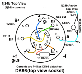
The DK96 or DK91 are Heptodes used as "frequency changers", i.e. Mixer/Oscillators taking in LW, MW or SW RF from tuned aerial loop or tuned ferrite rod and on the output at Anode the IF frequency (usually between 450kHz and 470KHz).
On the face of it you think you need 1j24b as an oscillator and a separate mixer. But there is a way to do this with a single 1j24b plugged into an unmodified DK96 or DK91 socket. Likely DK92 or DK962 also. On most Heptode Frequency Changers such as DK96 the anode volts are about the same as HT volts or G2 volts. There is no resistive anode load, just the IF transformer. Yet the anode current is very low (maybe only 200uA), but the g2 current might be 1.4mA. The g4 current might be 120uA. The Oscillator is output / drive on g2 and input/feedback on g1. I've established already that the rod pentodes work well as oscillators from Screen grid to control grid, but only if anode voltage is very low or anode disconnected. Given the "current mirror" characteristic between g2 and Anode below the pentode knee, that makes sense.
(click for full size)
What about the Mixer? I built an AM micro power generator (only a transmitter if you add an aerial). It used anode feedback, a "polycon" and MW ferrite rod for tuning/feedback. I established that using G3 as a mixer input the mixer gain to Anode doesn't depend much on anode volts, hence you get more modulation % AM at 12V HT than 40V etc. I wasn't sure about the G2 volts as the Invicta 29 I was testing with (uses a DK96) so I tried 22K, 47k Ohms and 4m7H coil and also nothing from G4 pin to g2. None of the variations made much difference. I calculated that 180k Ohms ought to reduce the Anode volts enough and that 10nF was plenty of decoupling across it. It worked. Less Mixer gain than the DK96. But very stable and sounds the same otherwise
Philips datasheet currents shown. In practice measured with a 1M Ohm input DMM the Anode volts is 6.7V. Which thus means about 400uA. Looking at the curves and assuming g1 on socket is about 0V (200mV below f-) the G2 would likely also be about 400uA. But it's running fine and very stable over all of MW & LW. Likely a specially designed circuit would perform better and 180K Ohms may not be optimal. But it does work in an unmodified radio as "plug in". So now I have an Invicta 29 with the DK96 (Ever Ready), DF96, DAF96 and DL96 (all Mullard) now for storage and LT current when battery 1.47V of 67mA. The original nominal 125mA is specified at 1.4V. The HT current is now 5.3mA rather than 6.7mA on Battery of 78V. However Mains operation is now a problem as the lower current draw causes LT to rise to 1.8V! So without some adaptation of the mains adaptor replacing tubes (valves) with lower current draw types may only be "safe" on Battery only sets. The 18 Ohms is optional since the 1j24b is nomally 1.2V and Dk96 nominally 1.4V. If using in a series chain a parallel resistor may be needed from pin 1 to pin7. Ironically the replacement of the DF96 with the 1j29b was the most problematic.
DK96 -> 1j24b with parallel RC in series with anode.
FinallyThe versatile "rod pentode" can be operated as a diode, (use g1 as anode, ground all other electrodes), Triode (connect g2 to Anode, and ground g3), Pentode, almost a Tetrode (bring g3 a couple of volts positive) and now even "plug in" to a socket intended for a Heptode/Pentagrid frequency changer.
|
|
Michael Watterson
22.Oct.11 |
7
I put a 470K "pot" and 39K series resistor bypassed with 10nF in series between 1j24b anode and the DK96 socket anode pin. Unsurprisingly at 39K and 505K there was no audio at all. (39K the Anode voltage is too high and the oscillator stops as g2 drops to small value, at 500K the anode voltage too low to get much current at all passing g2 and g3) Surprisingly the "loudest" setting was measured at 188K Ohms. Very close to my original and first tested value of 180K Ohms. I tried also 22pF instead of 10nF as the bypass on the resistor. With 10nF the tuning of the first IFT is very broad. But the other 3 coils are sharp enough. With 22pf it is not as sharp as the other 3 coils but much narrower. But of course a significant drop in gain. |


|
Hits: 8573 Replies: 0
1j24b various triode connections.
|
|
|
Joe Sousa
27.Dec.10 |
1
Fellow radiophiles: One of the characteristics of Russian Subminiature Tubes is a very efficient screen grid G2 design that takes only a small proportion (~10%) of the total plate current. This low G2 current makes it attractive to try various triode-connected circuits to achieve different values of triode intrinsic gain μ by choosing different feedback networks between the plate and G2. This concept of turning a pentode into a triode with a particular intrinsic gain μ is similar to the method of making a FET behave like a triode with a trioderizer circuit.
Having G2 as a low input current control element, leaves the control grid free to be used with very high impedance source circuits. The 45V source can be used independently from the negative feedback network to control the equivalent transconductance gm of the triode. The following curve trace families were taken with the Tektronix TEK575 transistor curve tracer and show several triodes that can be emulated with this pentode. Anode shorted to G2 gives the native μ=20. R1=3.3Meg R2=1Meg gives μ=80
Reducing NFB with R1=5Meg gives μ=104 Lastly, R2=10Meg gave μ=180
Note that the top trace in all of these plots is for G1=0V. The lower traces have negative G1 voltages in -500mV steps. But the control grid G1 remains non-conductive below -1V. See 1zh24b DC operation at low voltage for more details about G1 conduction. Best regards, -Joe |
 The basic concept is to provide external negative feedback (NFB) from the plate to the the screen grid G2, which is similar to the internal negative feedback from the plate of triode to the field surrounding the space charge at the cathode.


|
Hits: 3023 Replies: 0
1j24b filament efficiency.
|
|
|
Joe Sousa
27.Nov.10 |
1
Fellow radiophiles: Measurements comparing 1j24b vs 1j37b filament efficiency have been added to the series on Russian Subminiature Tubes. Regards, -Joe
|
End of forum contributions about this tube
| Data Compliance | More Information |