
1Ж37Б1j37b

|
|
|||||||||||||||||||||||||||||||||

|
Hits: 57195 Replies: 9
1.5V AM tube transmitter
|
|
|
Joe Sousa
03.Oct.09 |
1
Hello fellow Radiophiles,
I based the design of this simple transmitter on Gammatron/Gridless-Audion operation of the 1Zh37B Russian Subminiature Tube. The most useful characteristic of Gammatron/Gridless-Audion operation is the ability of the plate to draw current at low voltages. Keep in mind that the "plate" is the second control grid rod G1B. The remaining electrods, G2,G3 and A, are also connected to G1B because they contribute an additional 10% to total "plate" current This transmitter requires an AA filament battery, preferably of the NiCd or NiMH kind to better meet the rated 1.2V filament operation, and an optional high voltage Bplus source for the plate. The Bplus source is optional because the oscillator operates with Bplus between 0V and 18V, if the filament is operated with a 1.5V cell and the plate supply is referred to the positive cathode terminal. The transconductance with 0V at the plate is still a useable 40uS with a 500uA plate current. When the plate voltage is zero volts with respect to the positive terminal of the cathode, it is still up to 1.5V above the negative terminal of the filament supply. The commercially made Ferrite coil was construted with two windings: One with many turns and 740uH for tuning, and a small winding with a few turns to couple to a low impedance transistor input in a solid state radio. The turns ratio is about 7:1 and serves to step up the plate voltage from plate to grid. This high step-up ratio is necessary to overcome the intrinsic voltage gain mu=0.25. The net loop gain during the short bursts of plate conduction is 7*0.25=1.75. The modulation scheme is a very conventional plate modulation that is injected with a step-up 10x 8R-1K audio transformer at the plate. This transformer is only needed to achieve enough modulation at higher supply voltages. The transformer takes signal from an audio earphone output, not from a high impedance line level output. The Audio transformer bandwidth exceeds 15kHz with a 1kOhm secondary load, but the transmitted bandwidth is limited by the undriven Q of the resonant tank circuit. The Ferrite antenna is ideal to transmitt to radios with a ferrite stick or a loop antenna that is sensitive to the magnetic field. A short wire tied to the plate output can be used to transmitt to radios with a wire antenna that are more sensitive to the electric field. As will be shown below, this transmitter works best with modulation up to 50% for the higher frequencies, and up to 90% for the bass frequencies. Over-modulation, results in the shutdown of the oscillator with each negative trough of the audio input, and a delayed startup when the audio signal goes positive again. The high Q and narrow bandwidth of the tuned circuit is one of the characteristics that keeps the RF envelope from following the audio signal at high audio frequencies and high modulation. Prof. Dr.-Ing. Dietmar Rudolph has posted a good article on the problems with startup of triode oscillators.
Construction
The picture that shows the batteries includes a 0V battery for Bplus in the form of a shorted battery clip that was recycled from a dead 9V battery. The 1.5V cell you see with a 9V clip on it is used to run Bplus at 1.5V. The lid is kept closed with an embedded pair of neodymium magnets on one of the front corners of the box and lid. The box is made of soft Bass wood and was bought ready-made at a local crafts store. I added the two wooden posts to support the ferrite stick, and removed the original brass clasp to fit the variable capacitor, after chiseling out the wood. A matched capacitor and ferrite stick could have been recovered from a discarded AM transistor radio. This would give a fairly accurate frequency indication. In my case, the ferrite and capacitor came from different sources. Little knurled brass nuts always look very cute, so I used for the audio input. I have found it a good idea to add a small schematic to the finished project. Amazing how much you forget after a few months or years. Measurements and operationThe operating range is about 2 Feet (65cm) with Bplus set to zero volts. This a good range to demo an am radio. Rasing Bplus to 1.5V gives clean coverage for a table full of radios. If you want to cover a room or small apartment, you will need the 9V battery at Bplus. The first scope photo shows the RF envelope at the plate and after it is broadcast and picked up with a single loop. The 400Hz audio waveform is essentially the power supply to the oscillator. The second photo shows the classic XY display with audio fed to the horizontal axis and the modulated output is at the vertical axis. This display is shows non-linearities, percent modulation and other characteristics more clearly. 400Hz at 50% modulation shows no distortions. Note that the 20Vp-p RF envelope present at the plate on the left photo corresponds to a 140Vp-p RF envelope at the grid because of the 7x feedback stepup ratio of the ferrite coil. Audio modulation with 400Hz
Increasing modulation to 95% at 400Hz starts to show some distortion on the negative troughs that is only apparent if looking closely at the left end of the second picture
Increasing modulation to 110% shows that it takes some time for the oscillator to restart after it was extinguished with the negative audio peak. This is usually not a problem if the oscillator runs at constant amplitude and drives a separate modulator.
Audio Modulation with 4kHzIncreasing the modulation frequency to 4kHz produces a lot of distortion that is visible in the following two photos. The most distorted part of the RF envelope is in the regrowth portion of the cycle.
Reducing modulation at 4kHz to 25% makes the distortion disappear, but some linear modulation delay is still apparent in the XY photo on the right.
Going FurtherI have found that moderating the modulation level produces produces a very good sounding result. This is in part caused by most of the audio content being concentrated at the lower frequencies. Perhaps an RM member would like to try adding a modulation stage to this oscillator, while keeping the low voltage operation. If so, please share your results. If a modulation stage is added, the oscillating coil should be shielded to avoid radiating unmodulated energy. In keeping with an elegant design orientation, my favorite external modulator approach would be that posted by RM officer Konrad Birkner at Simplest diode modulator. Another alternative is the choice of tube. Other tubes with a low mu may be good candidates for this circuit, when used in reverse triode operation, with the input at the plate and the output at the grid. The rule of thumb in selecting an alternative tube is to look for a mu less than 10. Remember that the step-up ratio for the oscillating coils must overcome the inverse of the mu, or up to 1/10. Candidates for reverse triode operation could be the 6AS7, 01A, 201A, 45, 2A3, 1G4, DM70/1M3. The DM70 even glows green. Perhaps European members could contribute European part numbers. If your goal is single supply operation, then the tubes with the higher filament voltage at 3V, 5V or 6.3V have an advantage over those that run at 1.5V. One thing to consider in the selection of a common triode/tetrode/pentode for reverse triode operation is the magnitude of the grid current in forward bias. A simple sweep with a power supply will show at what point the grid current becomes excessive. O good upper limit is the rated max cathode-plate current in the data sheet. Solid state builders may like the low voltage operation, while still using a real, if not very special, 1Zh37B tube. Regards, -Joe Other AM transmittersExamples of transmitters posted by RM members can be found at: 1 Watt AM Transmitter (solid state) Home made AM transmitter with dual gate mosfet A survey of AM modulator/transmitters Another survey of AM modulators/transmitters Granco-ARC60 AM Modulator/transmitter runs off 12.6VDC. High Performance modulator with Resistance stabilized oscillator |
|
Joe Sousa
07.Oct.09 |
2
Hello radiophiles, This post was stimulated by Christian Bruckner's inquiry about Magnetic transmission. More related content was also posted by Konrad Birkner about the use of ferrite antennas. I used Google-Translate to read these German language posts Reception of Magnetic fieldsMany AM tube radios have inputs for an external wire antenna. Many have a loop antenna as an alternative, or in addition to the external antenna input. In later years, the loop antenna came to dominate AM tube radio design. Nearly all solid state AM radios used loop antennas. The loop antenna has two important advantages over wire antennas: 1-Loop antennas are usually smaller than the equivalent wire antenna. This is true for air loops, and even more so for ferrite loop antennas. 2-Most man-made noise in the AM band tends to be concentrated in the Electric field, so an antenna that derives it's signal from the Magnetic field is less likely to pick up noise. Some of the better AM radios even employ a grounded sheild over the ferrite loop to prevent pickup of the electric field by the ungrounded high impedance end of the loop. When you bring your hand near a loop antenna and you notice an increase in noise, you are probably injecting Electric field noise. Natural random noise power from atmospheric discharges is cut in half by the reception pattern of a loop, as it would be by a dipole, because a reduced amount of random noise power is received near or at the notches in the reception pattern. This -3dB improvement in SNR (Signal-to-Noise-Ration) is not dramatic, but worth having. The two reception notches that occur perpendicular to the axis of the loop virtual cylinder can also be used to eliminate reception from a distance station on the same frequency, or from a nearby point source of man-made noise. Transmission of Magnetic fieldsThe polarization (orientation) of the magnetic field of modern AM transmitters creates magnetic lines of force that are parallel to the earth. This orientation usually changes after reflections by the ionosphere. The typical AM transmitter antenna consists of one or more vertical radiating masts with a vertical reciprocating current flow at the transmission frequency. This current flow then creates concentric magnetic lines of force that are parallel to the earth. The horizontal magnetic field lines of this polarization, are the perfect match for receiving loops with a horizontal axis that are universal in AM radios. Given that most AM radios only need the magnetic field to work, why do AM transmitters radiate Electric field at a ratio to the Magnetic field that approaches the ideal free space impedance of 377 OHms? The answer is that you can't cover more than a few wavelenghts of distance with just Magnetic field or Electric field. It is necessary to radiate Electric and Magnetic fields at the antenna in the ratio of 377 Ohms, so more energy can be radiated at reasonable drive currents and votlages. The following graph shows how an Electric field or a Magnetic field emission becomes an emission with both fields at a ratio of 377 Ohms after a few wavelengths. You can see the full page scan with text, by clicking on the graph, but I no longer know the source of the scan. I think I got this scan from my colleague, and former Delco AM radio designer, Tom Hack. Note that the wavelenght at 1MHz is 300m (980ft). This very long distance makes it very reasonable to assume that all distances inside a home have negligible wave effects, and the fields can be understood as if they were static DC fields. Keep in mind that this is no longer true if you live in a 100m long castle!
Personal Magnetic transmissionThe arguments just outlined can be reversed for the personal use of small AM transmitters: The small AM transmiter should be purely an Electric field transmitter, or a Magnetic field transmitter. I chose the Ferrite antenna for the 1.5V AM tube transmitter to generate the magnetic field that nearly all my AM radios were designed to receive. The magnetic field transmission will also decay much more rapidly, with 1/distance^3, than a transmission with a 377 Ohm ratio of Electric to Magnetic fields with a decay of 1/distance . This is beneficial to reduce the reach of your transmission outside the region of interest, while maintaining a comparatively strong magnetic field locally. The little 1.5V AM tube transmitter includes a 10pF wire antenna hookup for radios that only use a wire for reception, such as this little 4 tube Kent set from 1940. This wire came with a soldered 8 foot wire antenna that is surprisingly sensitive, once it is streched out. The grid input end of the the tuned coil in the 1.5V AM tube transmitter swings on the order of 140Vp-p with a 9V battery at Bplus and a few volts with zero Bplus. The electric field in the vicinity of this end of the coil is enough for the little Kent radio to pick up if it is sitting nearby. The plate of the 1.5V AM tube transmitter swings 20V p-p with a 9V Bplus and about 0.5V p-p with zero volts Bplus. This is sufficent to drive several feet of wire through 10pF without significant detuning to the low impedance plate circuit. E-field transmission over short distances can be understood as the coupling of a weak capacitor, while M-field transmission over short distances can be understood as loosely coupled inductors. One extreme case of attempting to mismatch transmission impedance away from the 377 Ohm E to M ratio of free space is being exploited to transmit power over short distances, while avoiding radiating it to great distances. It is fascinating that impedance matching and impedance mismatching can be used to great advantage, depending on application: mismatching is ideal for local power transmission, while matching is ideal to maximise transmission over long distances. In conclusion: Pure E-field or pure M-field radiation is best for personal AM transmitters to strengthen the local "near-field" reception, while weakening distant "far-field" reception. Regards, -Joe p.s.: The formal letter to represent the magnetic field is H. I used M to avoid confusion for readers that are not familiar with electro-magnetic theory. Konrad Birkner uses the formal H in his post listed at the top. |
|
Dietmar Rudolph † 6.1.22
08.Oct.09 |
3
Small radios often use a loop antenna or a ferrite coil antenna. In the case of realigning such a receiver, the signal has to be coupled into its loop or ferrite coil antenna.
This clearly is a near field radiation or even nearly a magnetic coupling. Realigning this kind of receivers may be faciliated by placing the test loop on the test bench as suggested by the next figure.
Lit.: Ghirardi, A.A.: Receiver Troubleshooting and Repair, Rinehart, 1955 Regards, Dietmar |
|
Peter Veldman
05.Oct.13 |
4
hello i saw your design and you said that you could use a dm70/dm71
how does one conect the tube to work in this transmitter? i cant figur it out becaus the 1Zh37B has 2 controll grids and the dm71 has 1 could you help me with it?
|
|
Michael Watterson
05.Oct.13 |
5
The 1j37b is very much newer, cheaper and common than a DM70 / DM71. See eBay. |
|
Joe Sousa
06.Oct.13 |
6
Hello Peter: I measured the operation of the DM70 in reverse mode, which corresponds to the "Gammatron" mode of operation of the 1Zh37b. I posted the curve family for normal mode operation and for reverse mode under the DM70 tube page. The point of this little transmitter is the very low plate voltage operation. In this mode of operation, the plate and grid terminals are swapped, so that relatively high currents are obtained when low positive voltage is applied to the grid, which is used as the output terminal. The penalty of reverse mode operation is a drop in transconductance (gm) and intrinsic voltage gain (mu). The following plot, which I repeat here from the DM70 page shows that the transconductance of 5uS and mu=1/20 are simply too low to generate enough loop voltage gain to obtain oscillations with only a 1:7 coil step-up ratio. By comparison, the 1Zh37b has a transconductance on the order of 500uS and mu=0.4 in Gammatron mode with 9V at the output terminal.
In the original post I pointed out that the DM70 glows a pretty green, but that is only possible in normal mode operation with the positive output voltage applied to the plate, where the phosphor coating is present. See Michael Watterson's detailed post on the conditions for glow of the DM70. If your goal was to use the DM70 in a little transmitter that glows green. That could still be done with a new design with much higher supply voltage at the plate in normal mode operation. In normal mode, the plate may need more than 100V, given the relatively weak transconductance of this tube. Should anyone like to try any other triodes in reverse mode in this transmitter, the connections are as follows.
Triode grid: tie to 1Zh37b Gammatron plate point as shown in the schematic. The reverse mu of a candidate triode should be higher than the 7:1 step down turns ratio, or >1/7=0.143 for this tank circuit. The output impedance in reverse mode also needs to be lower than the tap impedance of the tank to avoid reducing the maximum possible voltage gain even further. The output impedance of the 1Zh37b in Gammatron mode is on the order of 1k-2k, while the tank tap impedance is on the order of 10k, which is negligible compared to 1k-2k. Regards, -Joe |
|
Michael Watterson
06.Oct.13 |
7
The iv-15 is a VFD indicator, much like the DM160. The method of light production is similar to the DM70 but as the filament, grid and anode are equally spaced along the length any variation of voltage on grid only causes overall brightness change, no variation in length of glow. The iv-15 can however also be "reversed", puting a fixed voltage on the grid and varying the Anode (plate). The output glow is then very dim, though it does vary slightly in length. The gain of the iv-15 is low to start with, so in the reverse mode it is very low. The other issue with DM70 or iv-15 is that though they can operate as low as 9V plate with positive grid, the current is very low, perhaps 0.2mA. Even at +45V the current may be less than 0.5mA so even with "push pull" very little power output is possible even if an oscillator is successfully made in "normal" mode or a reversed grid and anode "gammatron" like mode. |
|
Peter Veldman
09.Oct.13 |
8
hello about the glow i dont mind it but i have a dm71 lying around so i wondered if i could use it
the dm160? would that work or a ecc81? |
|
Michael Watterson
09.Oct.13 |
9
It would be difficult to get a DM160 to work and nearly impossible for a DM70. If you want to experiment with Gammatron/Gridless-Audion operation then order some 1Zh37B Russian Subminiature Tubes (1j37b) from Ukraine via Ebay. If you want to make a tube AM transmitter/modulator then two Pentodes (one triodised) (mimimum 3 x 9V batteries HT and single NiMH LT using rod Pentodes ) or an ECH83 / ECH81 (14V HT possible, 18 to 50V is better). Of course there are single ICs even "better". The single chip IC mixers can be "unbalanced" so you have AM carrier. |
|
Joe Sousa
12.Oct.13 |
10
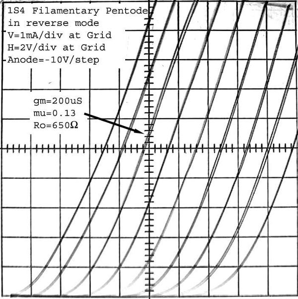
Hello Peter: Your question about what conventionally constructed tubes might be used as an alternative to the 1Zh37B as a tube transmitter that operates with 9V anode voltage, made me search for such a tube. The 1S4 and its twins (3S4, DL91, DL92) have a sufficiently low normal mode mu around 5 to operate with enough mu~0.2 in reverse mode. In reverse mode, the positive output element is the first grid and the other elements serve as the control element. Using the first grid as the positive output terminal is what facilitates high conduction at 9V. The negative biased screen grid G2 exerts over 90% of the control. The suppressor grid and plate have little control because of the shielding action of the screen grid G2. The suppressor grid is internally tied to the fillament and the unused plate is tied to G2 or grounded.
The output impedance of 650Ω is more than sufficiently low to drive the ~20k tank tap impedance. So we are left with getting the product between the reverse mode mu and the tank voltage step up ratio well above 1.
The measured reverse mode mu of 0.13 when multiplied by the 1:7 Voltage step-up ratio of the tank tap brings the closed loop voltage gain above one to guaranty oscillation. The realized voltage step up ratio varies somewhat from the turns ratio due to the additional impedance transformation effect in the uncoupled portion of the coils. This also makes the voltage step-up ratio somewhat frequency dependent. One important factor in controlling the effective step-up ratio is the positioning of the coil along the ferrite rod. Positioning the coil at the center of the rod as shown in the original transmitter, increases the coupling and step-up ratio to the maximum possible.
The following schematic shows the connections for the 1S4 in reverse triode configuration in this oscillator circuit.
The oscillation amplitude at the output anode grid G1 is only 4Vp-p, which is less than half the amplitude that was realized with the 1j37b. Much of this can be attributed to the much lower reverse mu of the 1S4, as they have nearly identical DC conduction of 10ma at 9V. The 1j37b mu=0.4 is high enough to cutoff the Gammatron grid with its p-p grid voltage and operate in the efficient class C, while the lower reverse mu of the 1S4 keeps the control plate from cutting off conduction, thus keep the operation in linear Class A.
The oscillations also have a tendency to stop near 500kHz. This is explainable by the frequency dependency of the step-up ratio. The photo shows a quick improvised construction to demonstrate the oscillations with the audio modulation transformer replaced by a wire.
Finding more tube alternatives For those that would like to see what other conventional tubes might work well as a low voltage transmitter, you should look for tubes that have mu<5 in normal mode triode configuration. The expected reverse mode mu is then >0.2. This leaves out high mu tubes like the ECC81 with mu=60, which would have a reverse mu on the order of 0.02. I also curve traced the DM160 in reverse triode connection and the mu was a very low 0.04, as might be expected from the normal mode mu=20. The reverse mode mu is too low to be overcome by the 1:7 tank step up ratio and the net loop gain remains below 1, which means that no oscillations occur. The IV-15 mentioned by Michael remains an intriguing possibility with normal mode mu around 7, but this would be a marginal case. If you try a conventional triode, remember that the output terminal that operates at +9V in this transmitter is the first grid G1, while the plate is the controlling input element. If using a conventional pentode, the second grid G2 is now the controlling element and all remaining elements should be tied to it. It is OK if the suppressor grid is internally tied to the cathode, as is the case with the 1S4. Pentodes often do not publish the normal mode triode-connection mu. One way to estimate the normal mode triode connected mu is to divide the nominal screen voltage by twice the recommended control grid bias. In the case of the 1S4, that would be 67.5V/(2*7V)=4.8. Remote cutoff pentodes also make poor candidates for reverse triode operation because part of the grid in these pentodes has a high mu, which can't be controlled in reverse mode. The high mu section of the grid looks like a dead shunt load in parallel with the low mu section of the pentode which can be controlled by the screen grid in reverse mode operation. Another possible candidate for operation at 9V is the multi-talented 1V6 triode-pentode. See the last three plots in "1V6 Curve Traces and Gammatron Action". These three plots all show substantial conduction of several mA at 10V with mu ranging from 0.6 to 4. But this is a relatively rare and expensive tube. Another class of tubes for oscillation at low voltages are the low voltage tubes that were designed in the late 1950's for operation from 12V car batteries. These tubes require wall power as they burn several Watts in their heaters. Tubes in this series include the 12K5 space charge tetrode and the 12BL6 and 12AF6 pentodes. These tubes should be operated in normal mode with the pentode input at the control grid and the screen grid biased at 12V and the ouput at the usual plate. The 6AS7 is probably the most common conventional triode that is found in reverse mode triode experimentation due to its low normal mode mu=2, which translates to a reverse mu on the order of 0.5. This post aimed to explore further how conventional tubes might be used in this 9V transmitter, but the 1Zh37B in the original transmitter above remains the best choice with its relatively high mu=0.4, good 10mA DC conduction at 9V and very wide low cost availability. Regards, -Joe |


|
Hits: 2797 Replies: 1
1j37b (1j37b)
|
|
|
Michael Watterson
08.Oct.11 |
1
Also known as 1ZH37b-r, 1sh37b-r and properly 1Ж37Б Useful information on these kinds of sub-miniature Rod Pentode tubes (valves): The 1j37b is still (2011) readily available to purchase as New Old Stock (NOS). Nützliche Informationen über diese Art von Sub-Miniatur-Rod Pentode Röhren: Die 1j37b ist immer noch (2011) leicht zugänglich zu kaufen (2011) leicht zugänglich wie Neu Alte Aktien Kauf (NOS) |
|
Michael Watterson
12.Oct.11 |
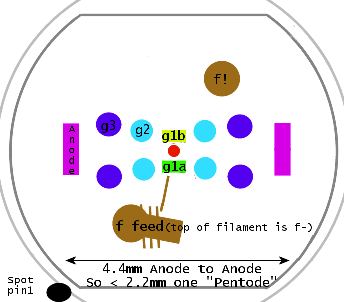
2
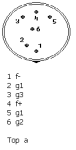
Cross-section showing single filament feed on top |
|
Hits: 2491 Replies: 0
1j37b filament efficiency
|
|
|
Joe Sousa
27.Nov.10 |
1
Fellow radiophiles: Measurements comparing 1j24b vs 1j37b filament efficiency have been added to the series on Russian Subminiature Tubes. Regards, -Joe
|
|
Hits: 3444 Replies: 0
1ZH37B(1J37B) More data sheets
|
|
|
Joe Sousa
03.May.10 |
1
Fellow Radiophiles, Sometimes different versions of a tube data sheet reveal different details. I have two loose data sheets that came with a ebay purchase of the 1ZH37B. I scanned these sheets and performed OCR of the Cyrilic characters with ABBYY express software. The original print quality was poor, however enough words were recognized to produce a useable translation by uploading the OCR result to Google-Translate. 1zh37b_sheet.pdf two page scan with OCR Russian text 1zh37b_sheet_EN.pdf Google translate output with English text, but no pictures diminished formatting. 1zh37b_3pages.pdf three page scan with OCR Russian text 1zh37b_3pages_EN.pdf Google translate output with English text, but no pictures diminished formatting The Google-Translate output is very difficult to save. So far, the only sucessful method I found is to print the output frame to a single very tall pdf page. The text can then be copied and pasted readily from this output. The two files above with EN in the file name have just the Google-translated English text. Regards, -Joe |
|
Hits: 2892 Replies: 0
1j37b - 1Zh37B Translated Data Sheet
|
|
|
Joe Sousa
03.Oct.09 |
1
MIT Electrical Engineering Student Dimitri Turbiner has kindly translated the 1Zh37B data sheet. The translation quality is excellent and we are all very grateful for Dimitri's contribution to the understanding of the Russian Subminiature Tubes with rod construction. Thank you Dimitri. -Joe |
End of forum contributions about this tube
| Data Compliance | More Information |