
1Ж42А1j42a

|
|
|||||||||||||||||||||||||||||

|
Hits: 2569 Replies: 0
1Ж42А data sheet in English
|
|
|
Joe Sousa
24.Nov.15 |
1
Fellow radiophiles: RM member Dmitri Faguet and I have translated into English two of the existing data sheets for the 1Ж42А (a. k. a. 1j42a, 1zh42a, 1sh42a) . I used ABBYY software to extract the Russian text with OCR, then I put the extracted Russian text through the Google translator and Dmitri performed the final proofing of the translation. See the pdf attachment. Regards, -Joe Attachments |
|
Hits: 4845 Replies: 0
1Ж42А photos - curves
|
|
|
Joe Sousa
22.Nov.15 |
1
Fellow radiophiles: Fellow RM member Michael Watterson found that the 1Ж42А (a. k. a. 1j42a, 1zh42a, 1sh42a) rod pentode has finally become available from a Russian seller at one of the auction houses. I bought a few samples. The X-84 marking on this sample suggests that it was made in 1984.
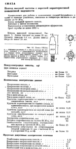
This rod pentode was designed for operation with 6V at the anode and screen grid, while drawing only 15mA from 1,2V at the filament. Other Russian rod pentodes were designed for at least 45V. As with any other tube that is designed for operation at low voltages, the internal mu of the 1j42a is low µg1g2=2.5 at 6V in triode connection and the total intrinsic gain in pentode connection is µg1A=16 for Anode voltages between 3V and 12V. However the Anode I/V curve has a flat spot at 6V, where the total intrinsic voltage gain from g1 to Anode should be some 10x higher, which is to say, more than 100. This flat spot is located where one would find the tetrode kink. The transconductance is nominally 400µS with g1=0V and g2=A=6V, g3=0V. Despite the low voltage operation, the data sheet still specifies the input resistance as 60kΩ at 60MHz, but the equivalent noise resistance is specified as a relatively large 90kΩ at 30MHz. This noise resistance is substantially higher than the 6kΩ equivalent noise resistance of the 1j24b.
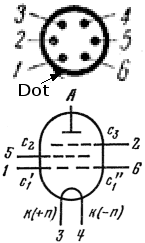
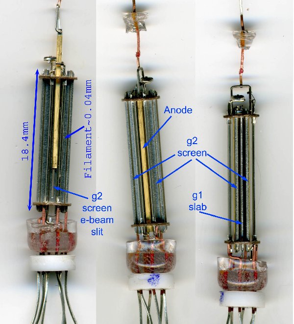
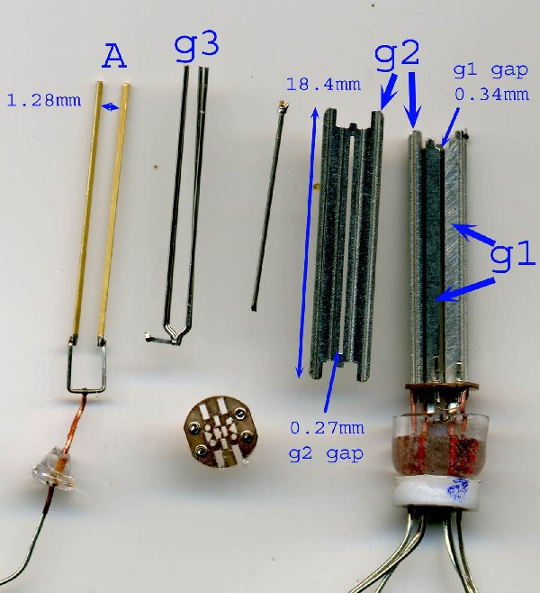
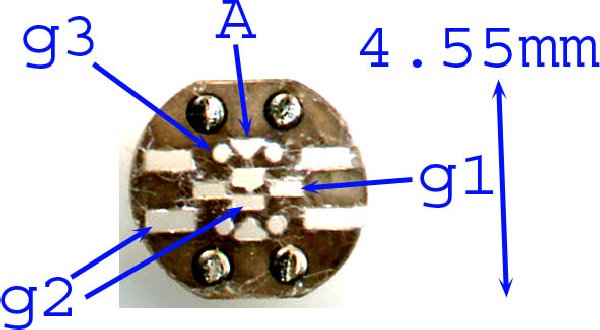
The construction is still gridless, but the low operating voltage requires tighter distances between the various rod elements. The overall active length is ~16mm. The tube was made more compact and the elements were made sturdier by replacing g1 and g2 rods with stamped metal elements. The control grid is made of two slabs instead of two rods gapped 340um on either side of the ~40µm filamentary cathode.
Each of the two control grid slabs is connected to separate external terminals for mixer service, as is the case with the 1j37b. The screen grid is now the largest element, consisting of two embossed plates with a central 240µ slit that accelerates the electron beam to the anode.
The suppressor grid g3 is the only element that is still made of 4 round rods.
The anode is a brass rod with a triangular cross-section. The point of the triangle is aimed to receive the bidirectional beam with two g3 rods on either side.
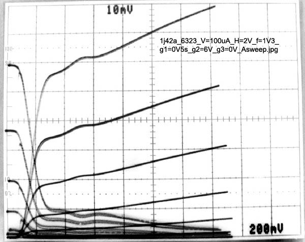
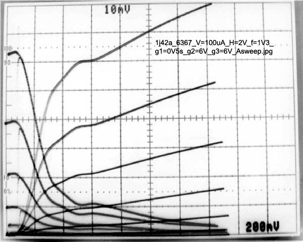
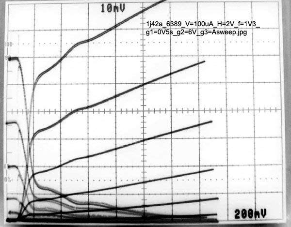
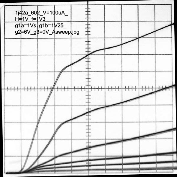
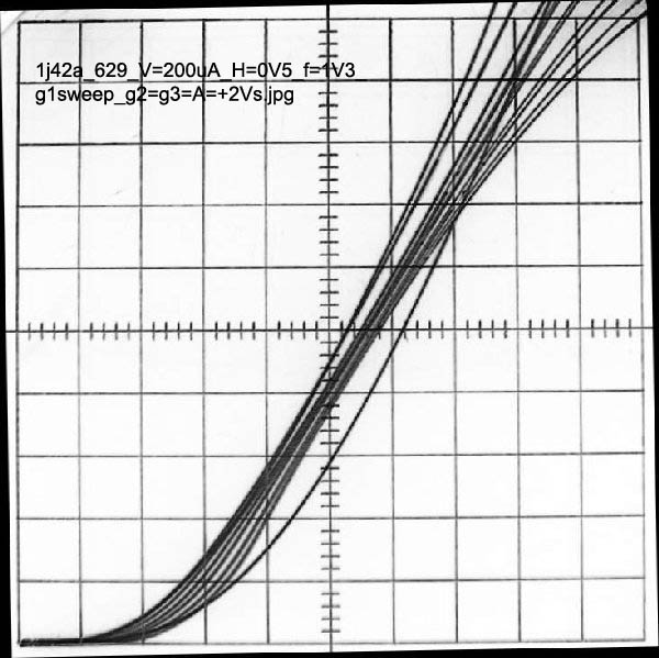
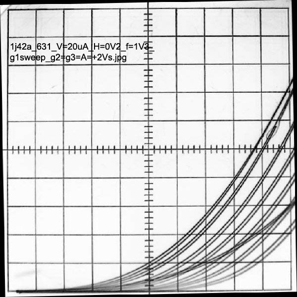
The following three curve families sweep the anode voltage with g2=6V, while showing the anode and screen currents. The control grid g1 is stepped in 0V5 steps. The three sweeps have the suppressor grid g3 set to 0V, 6V and tied to anode.
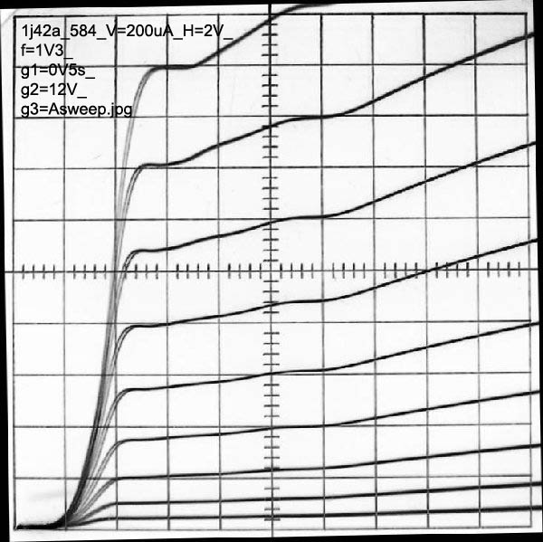
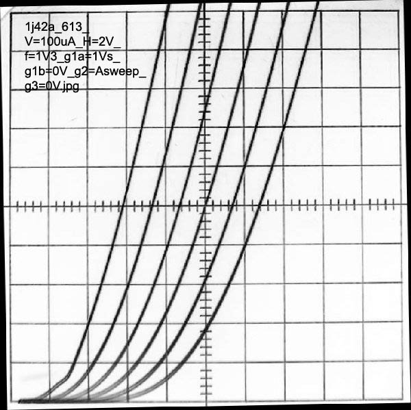
The following three sweeps show the operation with screen grid g2 voltages at 9V, 12V and 4V.
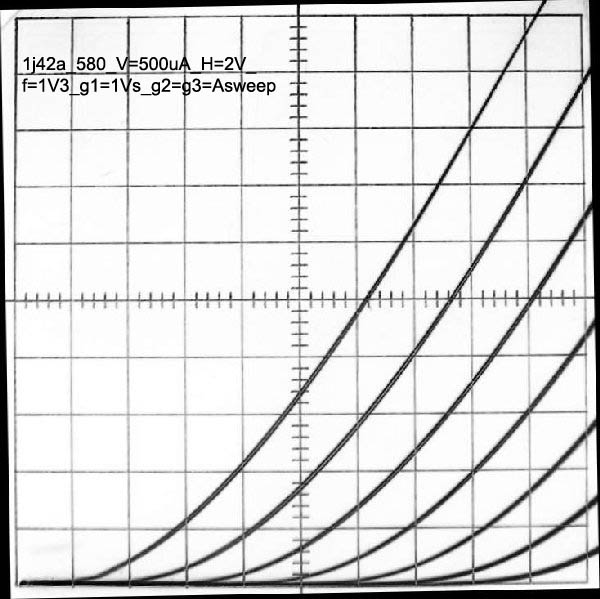
Triode operation with g2=g3=Anode
 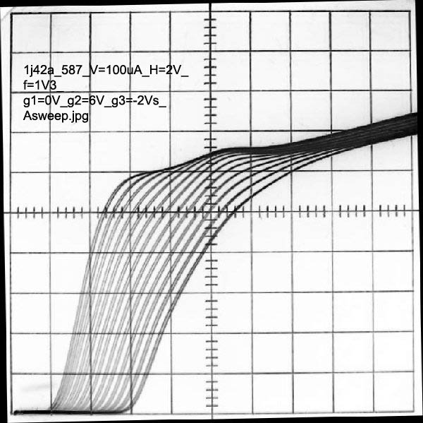
This sweep shows the relatively week control of the suppressor grid g3, in 2V steps, on anode current. The control grid g1 is grounded, the screen grid g2 is at 6V and the anode voltage is swept.
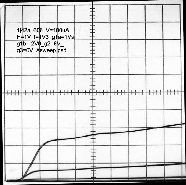
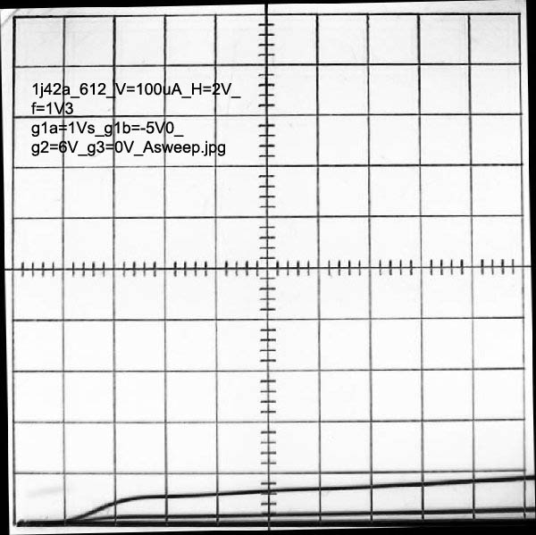
Mixer operation, with one half of the control grid g1a stepped in 1V steps and the other half g1b set at three bias levels of +1V25, 0V, -2V and -5V. In this example, the rf signal would drive g1a and the local oscillator would drive g1b.
A further illustration of the controlling effect of g1b on g1a. This time in triode connection.
Note the curious increase at g1a in gm and mu from 200uS and 1.6 to 400uS and 2.2, when g1b back bias is increased from 0V to -5V, but the triode anode voltage must also be increased from +6 to +12 to realize the benefits, because the triode is nearly cutoff with the anode at +6V and g1b=-5V.
g1a and g1b are identical and interchangeable.
Control grid g1 conduction as g2, g3 and the anode are stepped in +2V steps. Shown in two scales.
The two halves of the control grid g1a and g1b are constructed nominally similarly to the control grids of the 1j37b. Each control grid half in the 1j37b has a very remote cutoff characteristic that can be used for AGC control. The effect of each control grid half in the 1j42a is much sharper. In the case of the 1j37b, when g1b is biased negative, g1a transconductance drops with very little change to g1a cutoff, thus retaining the ability to resist saturation from large signals at g1a. In the case of the 1j42b, biasing g1b negative, will reduce transconductance at g1a, but also reduces the cutoff voltage at g1a, thus making g1a more likely to distort with large signals with a large g1b AGC bias.
If these tubes were used in a portable hybrid tube/transistor radio like the Emerson 838 from 1955 with 4V5 and 45V batteries, only low voltage batteries would have been needed, like 1.5V and 4V5. The 1j42a was only available in the former Soviet Union and apparently was never used for consumer goods.
Regards,
-Joe
|


|
Hits: 3798 Replies: 1
1j42a (1j42a)
|
|
|
Michael Watterson
09.Oct.11 |
1
This is a dual control grid rod pentode similar to the 1j30b and 1j37b. In Russian it's marked 1Ж42А See also Russian Subminiature Tubes for general Information. The 1j37b is down to 12V on Anode and G2 for operation and about 59mA filament. The 1j42a can be used with 6V HT and is only 15mA filament Please contact the Author if you know of equipment using it or stock for sale.
|
|
Michael Watterson
11.Oct.11 |
2
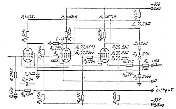
I found this Electrometer circuit for the 1j42a (1Ж42А) . I presume it would work also for the 1j37b (1Ж37Б).
|
End of forum contributions about this tube
| Data Compliance | More Information |