
48

|
|
|||||||||||||||||||||||||||||||||||||||||||||


|
Hits: 3403 Replies: 0
Edward W. Herold's first patent, the type 48 power tetrode
|
|
|
Jacob Roschy
30.May.11 |
1
RCA tube designer Edward W. Herold's first patent, the type 48 power output tetrode :
Patented Oct. 22, 1935 UNITED STATES PATENT OFFICE
2,018,362 ELECTRON DISCHARGE TUBE
Edward W. Herold. Bloomfield. N. J. assignor to Radio Corporation of America, a corporation of Delaware Application September 9. 1932, Serial No. 632,285 3 Claims. (CI. 250-27.5) This invention relates to a four electrode discharge tube of the screen grid type constructed to produce the results obtained with a pentode type of tube, and more particularly to a novel type or plate or anode structure which is substantially free from secondary electron emission so that the usual auxiliary means for suppressing this emission becomes unnecessary. In the pentode type of tube there are three grids, the first or inner grid to which the signal is applied, a second or accelerator grid and a third or suppressor grid. In such a tube the electron flow for a given control grid voltage is largely governed by the accelerating voltage applied to the second grid. Not all or the electrons accelerated by the second grid flow to it, in fact, most of them pass thru the second grid and eventually are received by the anode. These electrons under the influence of the anode voltage produce an emission of secondary electrons. The suppressor grid lying between the second grid and the anode and in the ordinary output pentode, connected internally to the cathode prevents for the most part the flow of these secondary electrons to the accelerator or screen grid. The presence of this suppressor grid, however, impedes the flow out the primary electron current as well as the flow of the secondary electrons in the reverse direction. This effect, while present at all anode voltages, is very striking at anode voltages of the order of 100 volts or less. For this reason the ordinary pentode is an inefficient output tube for use at these lower voltages. The present invention provides a structure which while suppressing the flow of secondary electrons does not appreciably impede the flow of the primary current. This results in a tube which is much more efficient than a pentode at low anode voltages. An object of the present invention is to provide an anode such that the electrostatic field surrounding those portions of the anode on which the primary electrons impinge will be sufficiently low that secondary electrons very largely return to the anode. Another object of the invention is to provide an anode structure which in itself combines the functions of the anode and of the suppressor grid of a pentode. Another object is to provide an anode structure which will inherently eliminate secondary emission therefrom, making unnecessary the use of a suppressor grid. Another object is the provision or a structure offering little interference to a beam of electrons approaching it but strongly resisting a flow of secondary electrons emitted from it under the influence or the first beam.
The invention will be better understood by having reference to the following specification and the accompanying drawing wherein : Fig. 1 is a plan view, partly in section, of an anode structure according to the invention; Fig. 2 is a cross sectional view taken on line II — II of Fig. 1; Fig. 3 is a perspective view of the grille member detached from the main anode plate; Fig. 4 shows a tube assembly using the anode of Figs. 1 and 2, and Fig. 5 is a plan view of the tube illustrated in Figs. 4. Referring now particularly to Figs. 1 and 2 of the drawing, the anode consists of a pair of similar trough-shaped plates 1 which at their ends are crimped to and supported by a pair of support rods 2. On each of the inner opposing faces of the plate members 1 is positioned a series of thin metallic slats 3 which may either form an integral part of the plate member or else may be placed closely adjacent and electrically connected thereto. These slats extend between the upper and lower edges of the plate members and are arranged in parallel relation and also with their planes parallel to the lines of electron flow from cathode to anode. As shown in Figs. 2 and 3 the slats or grille member may be fashioned from a continuous metal strip in the following manner: the terminal 4 of the strip, of a length equal to the width between slat sections, is shaped at right angles with respect to its adjacent slat section. The strip is then run back and forth in parallel relation to the extent of the length of the anode plate member with the desired spacing between slat sections. When the proper number of slat sections have thus been formed the strip is carried over the top of the formed slat sections and welded or otherwise fastened to the top connecting pieces 5 between sections, then around to the bottom of the slat sections and welded or otherwise fastened to the bottom connecting pieces 6, with the strip terminating at 7. The construction of the anode above described is such that the primary beam of electrons for the most part flows between the metallic slats and to the main body of the anode. That is, the electrons received by the anode are received into a series of boxes, the fronts of which are open. Since the back and the sides of the boxes are electrically of one piece of metal, the electrostatic field at the back of the box, that is at the anode surface proper, is very small and secondary electrons released from this surface are for the most part retained within the box and drawn back to the anode instead of being drawn to the other elements of the tube. At the same time this structure offers little increased resistance to the flow of the primary beam since the accelerating field is that due to the slats. A further reduction in secondary emission is obtained by a blackening of the above anode structure by means of carbonizing or in any equivalent manner. There is thus provided a simple efficient structure which enables the tube to function as a pentode altho it has only two grids, and enables a tube to be constructed which for a low anode voltage, is more efficient than a pentode. In some cases it may be desirable instead of slats to use wires projecting towards the cathode or to use any other equivalent means producing the same or similar reduction in field strength at the anode surface. It is also possible, in certain cases, to place the slats parallel to the grid wires and in the “electron shadows” cast by the grid wires, so that all of the primary electrons from the cathode stream would be received into the boxes of the plate and none intercepted by the slats. In the case of the tubes to be used at comparatively low frequencies and in particular for audio frequencies it may be found desirable to use the slats alone as anodes, in other words, to eliminate the solid part of the anode. This results in a structure the projection of which at the cathode, is very small and which permits excellent thermal radiation from the cathode. It may be found necessary to adjust the widths of the slats in accordance with the voltage applied to them in order that a sufficiently low percentage of the electrons will pass thru the slats without being drawn to them. In designing an anode of this type it is desirable to have the slats sufficiently close to produce the desired uniformity of a field and yet not so close that the edges of the slats themselves emit appreciable secondary emission. It has been found that slats approximately 120 mils wide, spaced 90 mils apart and made of 3 mil carbonized nickel give very satisfactory results. These slats are placed edgewise against the plate and have their length essentially at right-angles to the individual grid wires; this is to allow the electrons which have been deviated by the grid wires to make as unrestricted an entry as possible into the boxes or cavities formed by the slats. In Fig. 4 I have shown a tube construction which employs the novel anode structure and comprises highly evacuated vessel, preferably a glass bulb 8 having at the top a cylindrical dome 9 and the usual base (not shown) at the bottom. The bulb has a re-entrant stem 10 with a flat press 11 on which the electrodes are mounted. The anode 1 is carried on the stem by two support rods 2 which extend from the press and engage the anode wings 12. Within the anode and coaxially therewith is positioned the uni-potential cathode 13, containing the heater element 14. Surrounding the cathode and coaxial therewith is the control grid 15 carried by a pair of support rods 16 projecting from the press, at the other end circuit the grid a circular sleeve member 17 is carried by side rods 18 of heavy copper joined to the support rods 16 and about which the grid wire is wound. The sleeve member extends into the dome portion of the envelope above the electrode structure and it functions as a heat radiator whereby the grid wire may be kept sufficiently cool to prevent harmful primary emission. The grid construction just described is the invention of D. Y. Smith, and forms the subject matter of a co-pending application, Ser. No. 632,297, filed Sept. 9,1932, and assigned to the same assignee as the present application. Surrounding the control grid and coaxial therewith is the second or screen grid 19 which may be of usual construction. Two insulating bridges or spacers 20 and 21 extend between the rods 2 near the upper and lower ends of the plate electrode 1. The top spacer 20, preferably of sheet mica, fits into the dome 9 well enough to prevent lateral movement of the electrode mount. The lower spacer 21 is preferably an oblong sheet of mica. The two spacers are held in place at the ends of the plate by metal bands 22 which clasp the spacers and are secured to the wings of the plate. The cathode sleeve and the side rods of the two grids fit into holes in the mica spacers and are held in fixed spaced relation by the spacers. The leading-in conductors 23, 24, 25, 26 and 27 for the anode, screen grid, heater, cathode and control grid respectively, are connected to the base pins or terminals (not shown) in the usual manner. While I have shown and described the preferred embodiment of my invention, it is, of so course, understood that other structural arrangements may be used without departing from the scope of the invention as covered in the appended claims. What is claimed is: 1. An anode structure for an electron discharge tube comprising a flat plate member, a pair of vertical support rods secured to the sides thereof, and a thin continuous metal strip, which commences at one end of the plate with its edge fastened to the plate surface, wound zig—zag fashion between opposite ends of the plate in parallel relation to said support rods, and forming a plurality of open-ended rectangular troughs, adjacent ones of said troughs being open at opposite ends, the remainder of the strip being carried along the opposite ends of the plate to close the open-ended troughs. 2. An electron discharge tube comprising a cathode, a helical control grid surrounding the cathode, a helical screen grid surrounding the control grid, an anode electrode in the form of a plate surrounding the screen grid, and a plurality of parallelly arranged metal strips mounted on the inner surface of and at substantially right angles to said anode electrode. 3. An electron discharge tube comprising a flattened indirectly heated cathode, a flattened helical control grid surrounding the cathode, a flattened helical screen grid surrounding the control grid, a flattened anode electrode in the form of a plate surrounding the screen grid, and a plurality of parallelly arranged metal strips mounted on the inner surface of and at substantially right angles to each of the opposing faces to of said anode electrode. Edward W. Herold
|

|
Hits: 4345 Replies: 2
48 Low mu=2.5 Tetrode
|
|
|
Joe Sousa
19.May.11 |
1
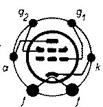
Fellow Radiophiles: The 48 Tetrode from 1932 by RCA was designed with an unusually low mu=2.5 between G1 and G2 or in triode connection. This low mu enables a high plate current flow with a relatively low voltage at G2. The standard curve traces in the RCA data sheet were plotted with G2=96V, and show a 1.5kΩ load line for audio power output of 2W with the plate also powered from 96V. The 30V/400mA heater was designed for series string operation in 117VAC/DC radios. The unique plate structure of this tube uses six ridges inside the plate to trap secondary emission. This nearly completely eliminates the tetrode saddle and widens the plate voltage swing to lower voltages than would be possible with a conventional power pentode. In a recent email exchange, tube historian Ludwell Sibley contributed this note about the origins of the 48 Tetrode and Edward Herold's invention of it's anode structure in US patent 2018362 granted to RCA:
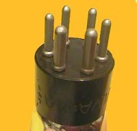
Haw! I have an RCA 48 whose design of the top mica makes it hard to look inside, but under the right lighting the eight ridges are indeed visible. The mount design differs in some details from that in the patent but that’s not fatal. I also have a couple of Philco-brand 48s (most likely of Sylvania or National Union origin) that are easier to observe. These have six ridges.
Herold got the patent, but ascribes design of the tube to another. His historical article in “AWA Review” Vol. 7, says, “I was asked to determine whether the 1929 tetrode screen-grid tube, type 24, could be recommended as a negative-resistance called the dynatron. The dynatron made use of secondary emission to produce an anode current that decreased as the voltage increased. After testing hundreds of tubes, made at different times, often with different anode materials, it was clear that no such recommendation could be made. However, I did learn a lot about secondary emission and about negative resistance. The secondary-emission knowledge helped me make an early invention [cites your patent], an anode with a series of slats to suppress secondaries. Such an anode was used by Sam Dodge in designing the type 48 power tetrode. The negative-resistance aspect stimulated a side-line interest in that subject and led to a Proceedings of the IRE publication [cites Vol. 23, 1935, pp. 1201-1221] and to a new use for the types 57 and 6D6 to obtain negative transconductance and negative resistance [cites RCA App Note 45].”
Our own Jacob Roschy had this to contribute in the same email exchange: Hi Joe, This morning I took a few shots of the 48, I hope you enjoy ! [ see uploaded top views in 48 page] I wonder why this principle came to oblivion after the 48 ? Probably the producing costs were higher as of the usual beam power tetrode ?
Some 30 years later, these plate ridges became reinvented, as someone must have thought, if one combines these plate ridges with the beam focus frame of the BPTs, a much better screen-grid output tube must result.
The PL300 has also this construction, as well the PL509 and the PL519. [...] Lud had a further contribution in the Tube Collector Association Yahoo newsgroup on the 48:
You might compare the 48 with three beam-power tubes specifically intended
I once reprinted an article on use of tubes by the Western Union Telegraph Lud I obtained a NOS 48 by National Union from Jim Cross at Vacuumtubesinc.com. Jim is also the current Chairman of the board of directors of the Tube Collectors Association. Fortunately, this National Union 48 has a similar structure to the RCA. (Raytheon also marketed a 48, but it was a Pentode of comparable characteristics, but a characteristically softer Plate knee region) In an email exchange with RM member Paul Reid, he pointed out the use of this tube in 32VDC farm radios. See the Silvertone 4612A from Sears, for example. This application takes advantage of the low mu=2.5, in operation with only 32V at the screen and plate, as might be found in an American farm radio that got it's power from wind mill charged batteries. While the plate draws a nominal 52mA in class A operation from 96V, it still draws a usable 15mA from 32VDC between cathode and G2+Anode. This much plate conduction at 30V would be difficult to obtain even with a space charge grid, especially if the low plate knee of the 48 is taken into consideration. I plot here the curve traces for my NU 48 operating with the screen G2 at 96V, 32V and 26V.
Note how dramatically reduced the available power output is, when the G2-cathode voltage drop is cut 32V. The 48 was usually configured in class AB push-pull to deliver about 3x more power, up to 400mW. Some designs included a bias resistor at the cathode that raised the cathode about 6V, thus reducing the cathode to G2 drop to 26V, and the single ended class A power was thus dropped to 80mW and the class AB push-pull power was down to 250mW. A reasonably efficient speaker can deliver plenty of volume to fill a room with 250mW to 400mW of driven power.
Paul Reid reminded me that the Langmuir-Child 3/2 power law for plate current as a function of Screen grid Vg2 and control Grid Vg1 voltages predicts the DC bias point quite well. If there is a set of Screen and control grid voltages and plate current, then a new plate current can be calculated for a new set of voltages without having to know the perveance of the tube. When reducing the Screen voltage, the control grid bias should be reduced in a similar proportion, so that it remains approximately half-way to cutoff.
The 48 curves show 15mA plate current for 32V and 10mA for 26V at the screen G2. This agrees well with the calculation result of 17mA and 10.6mA.
A 50C5 is compared here in the last calculation because it draws similar Plate current levels from similar screen grid voltages, yet the much higher mu=6 reduces the current disproportionately at 32V. Note that the grid swing of the 50C5 will be also limited by the start of conduction around -1V and complete cutoff will be experienced at 32V/6=-5V with a 32V supply. Regards, -Joe |
|
Joe Sousa
09.Jun.11 |
2
Radio Age editor Ed Lyon had this to say in a private email about the Pentode variant and the application of the 48 in American farm radios:
I had thought that there were more brands that copied Raytheon’s design, but maybe they were all made by Raytheon and were rebranded. I notice that RCA and Sylvania differed slightly, one (RCA) having 8 ribs in the anode, the other having 6. That is some pretty amazing resourcefulness on Ed's part, and a very understanding mother to give up so many jelly jars. The house wiring for the 32V lighting system must have been quite heavy. Regards, -Joe |
|
Paul Reid
19.Jun.11 |
3
> G2 drop to 26V, and the single ended class A power was thus dropped to 80mW and the class AB push-pull power was down to 250mW. The Silvertone 4612A schematic linked here has a Power Output spec:
Undistorted: 0.15 watts
Maximum: 0.32 watts
On your graphs, I figure 20V 20mA peak swing. In class B (or AB) this is 0.4W peak (or squarewave), 0.2W Sine. With transformer and other stray loss, and conservative interpretation of "undistorted", this 0.2W matches the 0.15 watts claim. The 0.32 watts number is likely gross distortion, essentially square-wave. > Langmuir-Child 3/2 power law for plate current It may be more useful to think "cathode current", not "plate current", when applying the space-charge equation. With just one positive electrode, as in a diode, and in a negative-grid triode, no difference. When you start throwing multiple electrodes positive, you must consider their relative leverages (Mu) and voltages to derive an equivalent voltage, then their relative capture-areas (not commonly known) to estimate the division of current between electrodes. Yes, the engine-generator lighting system AND the wind-generator system were common on wealthy US farms 1920s-1940s. The engine only needs gasoline and runs any time. The windmill works for free if you have wind. In the Midwest, wind was intermittent and fuel was readily available. In Kansas it is a long way to the store but the wind never stops. Either source wants storage. Inefficient to idle a 600W engine for one 25W lamp. Even in Kansas the wind may stop. Storage comes in 2V units and at the time a separate glass jar for each 2V unit. OTOH copper costs more than insulation so distribution favors higher voltage. So the systems-engineering problem is to balance number of jars versus fat wires. In a homestead, the loads are mostly small and nearby. 32V (16 jars) seems to be the accepted voltage for small units. (There were also 110V DC units for larger systems.) > The house wiring for the 32V lighting system must have been quite heavy. Well, serious, but probably no fatter than urban houses. The "competition" was candles and kerosene lanterns. Only the biggest kerosene lanterns had the output of a "normal" incandescent. I have 240 Watts (equivalent incandescent) of lights on right now; a 1920s farmer might be thrilled with two or three 25 Watt bulbs. Also the NEC suggested 2% voltage drop is for negligible flickering in systems with large intermittent loads; a farm system may have no large loads and be quite understanding of flicker when loads are switched on/off. A 30-foot 2-wire circuit in #12 (same as good 120V wiring) is about 0.1 ohms. For 10% drop at 32V that is 29 Amperes or 900+ Watts. Turning 25W-50W lamps off and on would have nearly no effect on other lamps. I see Delco sold a clothes-iron... taking this at 600 Watts it would cause a perceptible dip when turned on (around 6%), but this may be preferable to firing-up the wood stove to heat a sad-iron. I could see a #12 wire run from cellar to kitchen, and #14 for general lighting. No more wire than a city-house, perhaps less because the large cost of fuel and batteries discourages excess use. |


End of forum contributions about this tube
| Data Compliance | More Information |