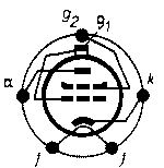
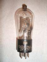
radiomuseum.org
Please click your language flag. Bitte Sprachflagge klicken.

UY224

Information - Help 
ID = 2585
       
Country:
United States of America (USA)
Brand:
Developer: Westinghouse El. & Mfg. Co. - see also Canadian W. 
Tube type:  Screen-grid Tetrode   RF/IF-Stage 
Identical to UY224 = 224 = FY224 = PH224 = F242 = SY224 = 124 = PU024 = MY224 = F224 = 222AC = D224 = ER224 = 57T224 = AC22 = BY224 = 122AC = TS224 = VY224 = CL-24 = Ray-224 = GY224 = OKY-224 = GSY224 = C-224 = T-24 = T-24-AC = A.C.224 = A224 = T-224 = AC224 = Y224AC = M24A = PAC224 = PM224 = EY624 = UY624 = 24
Similar Tubes
Normally replaceable-slightly different:
  24A ; AC24 ; ASX2240 ; FM500 ; R224_Rogers ; RY224 ; SY224A
Other class quality (otherwise equal):
  NU-24S
Other characteristic (electr. data):
  245A_W.E.
Other base:
  24_Coronet
First year 20.Apr.1929 Saga of the Vacuum Tube, Tyne page 321 and 322.
Predecessor Tubes 122AC   SY-222  

Base UY-Base, 5 Pins (USA, April 1927) (Codex=Ha) Top contact with a cap.
Was used by Radio/TV-reception etc.
Filament Vf 2.5 Volts / If 1.75 Ampere / Indirect / Specified voltage AC/DC
Description

According to Tyne, page 321, this first US AC screen-grid tetrode, the UY224, later called 224 or 24' in the US was introduced in April 1929. It derived from the first US indirect heated triode UY227 from 1927 with the same heater-cathode combination. The oxide-coated filament operates at 2.5 volts AC or DC, taking 1.7 amperes. With 180 volts on the anode (-1.5 inner control grid, 75 volts on screen grid) is resulting 4 milliamperes, the amplification factor is a bout 420, the anode impedance 400 000 ohms and the mutual conductance 1050 micromhos. Direct capacitance between anode and control grid is less than 0.01 picofarad which made Neutrodynes obsolete beginning in 1929.

 
Dimensions (WHD)
incl. pins / tip
x 123 x 45 mm / x 4.84 x 1.77 inch
Weight 50 g / 1.76 oz
Tube prices 1 Tube prices (visible for members only)
Information source Saga of the Vacuum Tube, Tyne   321, 322 & 343
Tube Lore (II)   p. 26 & 30
Taschenbuch zum Röhren-Codex 1948/49

448_12.png UY224: Telefunken Werkstattbuch
Wolfgang Bauer


Just Qvigstad
type24plategraph.png
UY224: Cunningham Radio Tubes Manual, 1932
Tonino Giagnacovo

Usage in Models 11= 1929? ; 57= 1929 ; 2= 1930?? ; 9= 1930? ; 25= 1930 ; 3= 1931? ; 49= 1931 ; 2= 1932? ; 6= 1932 ; 7= 1933? ; 1= 1933

Quantity of Models at Radiomuseum.org with this tube (valve, valves, valvola, valvole, válvula, lampe):172

Collection of

 
uy_224.jpg

UY224
 

Variants

The UY224 was developed and produced by Westinghouse. One of these tubes is shown in the book "70 Years of Radio Tubes and Valves" by John W Stokes, page 65 and 66. See also in the Saga from Tyne, page 321 and 322. Later developments had the assembly mounted vertically, to the base. See also this article.


Forum contributions about this tube
UY224
Threads: 1 | Posts: 1
Hits: 3184     Replies: 0
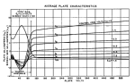
UY224 plate characteristics measured with a curve tracer
Tonino Giagnacovo
28.Apr.12
  1

This is a plot of the plate characteristics of the screen grid amplifier tube, measured with a Tektronix 577-177 curve tracer (577 is the display unit, 177 is the standard semiconductors test fixture).

As can be seen, negative-resistance section is clearly visible, when the plate voltage is between 10 and 90 volts, which was the screen-grid voltage.

Graph was annotated with the curve tracer controls settings, as follows:

 - control grid step voltage: 2V per step
 - Y-axis: 1 mA per division
 - X-axis: 20V per division

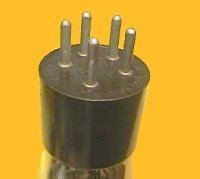
Two external power supplies have been used to deliver power to the screen grid (90V) and the heater (2,5V).

It is very important to adjust the current limiter into the screen grid, as in some conditions during the sweep, and when plate voltage is disabled, it is easy to exceed the maximum permissible power dissipation.

The following image shows the test setup:


The following image shows as the plot is displayed on the screen of the curve tracer.


The negative-resistance portion of the plate characteristic was utilized to realize the dynatron oscillator (refer to RCA patent #2067366).

In the RCA cathode ray tube television receiver prototype of 1931, two dynatron oscillators equipped with UY-224 tubes provided the line (2880 Hz) and frame (24 Hz) signals to the magnetic deflection coils of the CRT.

A good description of this interesting television receiver can be found in the following websites:

RCA first CRT Television Receiver - 1931

Earlytelevision - RCA Television Receiver - 1932

Technical details of this television receiver are described in a paper by V.K.Zworykin - Description of an Experimental Television System and the Kinescope, Proceedings of the IRE, vol.21, no.12, pp.1655-1673, Dec. 1933 and reprinted in the Proceedings of the IEEE, vol.86, no.5, May 1998.


UY224
End of forum contributions about this tube

You reach this tube or valve page from a search after clicking the "tubes" tab or by clicking a tube on a radio model page. You will find thousands of tubes or valves with interesting links. You even can look up radio models with a certain tube line up. [rmxtube-en]
  

Data Compliance More Information