radiomuseum.org
Please click your language flag. Bitte Sprachflagge klicken.

Wunderlich

Information - Help 
ID = 3080
       
Country:
United States of America (USA)
Brand: Arcturus Radio Tube Co.; Newark, NJ
Developer: Arcturus Radio Tube Co.; Newark, NJ 
Tube type:  Wunderlich Tube   Detector 
Identical to Wunderlich
Similar Tubes
Normally replaceable-slightly different:
  WunderlichA
Differences not known by us:
  29
First year 1932 Saga of the Vacuum Tube, Tyne 365

Base 6-Pin-Base U6A, old, USA
Was used by Radio/TV-reception etc.
Filament Vf 2.5 Volts / If 1 Ampere / Indirect / Specified voltage AC/DC
Description

A triode had two intermeshed grids equally spaced from the single cathode and the plate. Used as a full wave detector (am) with additional LF-amplification. This was knwon as a "Special Detector"

 
Text in other languages (may differ)
Dimensions (WHD)
incl. pins / tip
x 103 x 38 mm / x 4.06 x 1.50 inch
Weight 34 g / 1.20 oz
Information source Tube Lore (II)   p. 31

tubesockel_klein_wa6p_11.png Wunderlich: W.H.
Wolfgang Holtmann


Just Qvigstad
Usage in Models 2= 1932? ; 14= 1932 ; 1= 1933?? ; 2= 1933? ; 15= 1933 ; 6= 1934? ; 8= 1934

Quantity of Models at Radiomuseum.org with this tube (valve, valves, valvola, valvole, válvula, lampe):48

Collection of

 
img_20130903_205621_2061646941.jpg

Wunderlich
 

Forum contributions about this tube
Wunderlich
Threads: 3 | Posts: 4
Hits: 3706     Replies: 1
  Wunderlich operational details
Joe Sousa
13.Sep.11
 
  1

Fellow Radiophiles:

There is a misconception in the usual understanding of plate ripple performance with push-pull detection in the Wunderlich. With perfectly matched drives and grid gains, with the plate biased for linear audio amplification, there is no 2x carrier ripple at all at the plate, even without any capacitor filtering at the plate.

As conditions deviate from the ideal, the difference in gains between the two grid paths will produce a small ripple at the carrier frequency. With larger signals, say, when  enough of the 3/2 gm power law is traversed for 10% distortion, a 2x carrier signal will emerge at the plate as each positive peak is amplified with a different gain from the negative peak between the two grids.

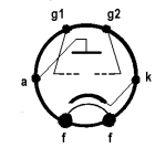
Input loading of the peaks will also produce this slight distortion which results in 2x carrier content at the plate. All this is true for an unmodulated input carrier with RC biased grid leak detection. The capacitor in the RC grid leak is essential because it keeps the grids DC-biased at mid carrier amplitude. When modulation is applied, then there will be a small carrier frequency ripple that has the amplitude of the audio increment from cycle to cycle. The unfiltered plate ripple will be greatest with 100% audio modulation at fastest modulation frequency of 4kHz.
The center tap of the driving transformer, where the AVC voltage is picked up, has the usual detection ripple across the RC grid leak, but at 2x the carrier frequency. For these measurements, I chose a very large grid leak cap of 0.1uF to eliminate all ripple at the grid leak RC, because I wanted to look for ripple at the plate that was only caused by grid imbalance or non-linearity. The Carrier component in the second photo is due to the slightly different grid gains, while the smaller 2x carrier component is due to slight non-linearity caused by the 24Vp-p swing at each grid. With the audio gain from the center-tap running approximately at 10, the 24Vp-p carrier only survives as a 10Vp-p signal at the plate, this is a 1/24=27dB reduction in carrier amplitude at the plate. A manual trim of the relative input grid amplitudes could have reduce the output carrier, to the point that only the 2x carrier component survives at the plate. 

The low mu=12 for the two grids driven together, as they are driven by the audio signal developed at the grid leak, and the plate bias via a large resistor to a high Bplus and effective AGC, should eliminate the cutoff type of distortion that is common with triode grid leak detectors driven with large signals with a low fixed bias at the plate, as was the case with battery sets of the 1920's. It would take 250V/12=-21V at both grids to cutoff the Wunderlich plate in the schematic shown above.

If the capacitor in the RC grid leak were removed, and the resistor were of sufficiently low impedance for a fast time constant, including parasitic capacitance, to follow the carrier cycle by cycle, one of the two grids would always be forward biased and we would have a very good carrier frequency doubler, as the plate current would appear full-wave rectified.

This photo shows this principle with 60Vp-p at each grid but with an input frequency of 160Hz to insure accurate fullwave tracking at the grids.

This insight came up from my design effort with the class AB p-p design of the Gammatron output stage in Sputnik.

Curve traces

This curve tracing super-imposes the two grid families in two colors. Note that the mu=6 for each grid is about half that for both grids, which is 12 as seen in the plot on the left. The grid match is best at lower grid bias levels.


The following plots show that a negative bias on one grid causes the curve family for the other grid to be shifted to the right. The second plot has a -20V bias on one grid, which caused with curve family for the other grid to move it's zero bias trace to the -18V position. This shows that the fields of the two grids add fairly linearly to control plate current in this 0-20V range.


This plot shows Gammatron style operation of the Wunderlich, where the plate is tied to one grid for the output voltage sweep, while the other grid is stepped at -2V/step. Note that the horizontal scale is reduced to 2V/div. Nearly all current in this plot flows through the grid that is tied to the plate. The plate carries little current.

This illustrates the potential application of the Wunderlich as a more efficient alternative to a space charge tetrode in low plate voltage applications. Space charge tetrodes employ the first grid as a space charge grid that draws a wasted current that is much larger than the plate current.


The following three plots sweep one grid while stepping the other grid with negative steps, while the plate is held fixed at 0V, +50V and +200V. Note how the effect of one grid over conduction by the other grid is neutralized by positive Anode voltages. These plots are useful to predict detection behaviour at the grid.


It seems that the salient feature of the Wunderlich, as compared to a conventional grid leak detector, is that there is much less carrier signal current at the plate. A filter cap can be added to the plate, but this already functions as the second pole in the envelope filter.  The very effective rejection of the carrier means that a faster grid-leak can be used with higher ripple because there is a second opportunity to filter without danger of diagonal distortion at the plate. The nearly constant and low impedance of the plate eliminates all danger of diagonal distortion there, thus making it a preferable spot for filtering. The plate impedance will be constant on a steady state basis, but will increase for stronger signals, as the grid leak circuit generates a negative grid bias.

After seeing the Wunderlich in action, it is clear to me that it can be functionally duplicated with a 12AE6 or 6BF6, which are triode-duplex diode tubes with comparable mu and gm to the Wunderlich. The connection would be slightly different with the two diodes driven by the ends of the coil and the grid tied to the centertap of the coil. This kind of hookup should make the operation of these two tubes nearly indistinguishable from the Wunderlich. A triode with three built-in diodes could emulate the Wunderlich B. The extra diode in the Wunderlich B serves as positive clamp to eliminate the chance of driving the AGC voltage positive in an amplified AGC scheme, which would induce signal path attenuation, thus inverting the AGC polarity, with the potential for latchup or AGC instability.

References

Die Wunderlich Röhren by Wolfgang Holtman (I read this German language post with the Google translator)

Questions about the Wunderlich tube by Wolfgang Holtman

"The Wunderlich Detector" by Ludwell Sibley, Tube Colector December 2006 Vol-8, no6, p33. Lud's article includes an extensive list of 12 references, many of which are contemporary with the Wunderlich tube.

"Wunderlich's B tube" by Ed Lyon, Radio Age Jan 2000 pp. 1, 3, 8-9.


Ed Lyon was very kind to lend me his Wunderlich detector for these measurements. Thank you, Ed.

Best regards,

-Joe

Ernst Erb
02.Apr.12
  2

At the moment we show about 40 models with Wunderlich tubes and 14 different types of tubes. In many cases it is the same tube with other designation but as a reference work we have to show all.

This type of a Wunderlich tube is the most known - with nearly 40 models. You find the models by clicking the tube and then scrolling down the tube page to click the presented models, sorted by model year.

But we find also a car radio from Sparks-Withingon, Sparton 34 with the type 70. This was confused with the type 70 current regulator - until a guest, Ron Wing, Wichita, KS, USA, told me. He added: "In the book "The Collector's Vacuum Tube Handbook" by Robert T. Millard, The Sparton Model 34 is given as the only known model that used a 70."
He used the contact form, an easy way to bring in such corrections.

By the way: The Wunderlich A with 5 pin and a top contact must have used also in radios I believe - but we have not yet listed a model for it.

Lud Sibley published an article "The Wunderlich Detector" in the TCA Tube collector bulletin Volume 8, Number 6 - December 2006 about "A discussion of circuits, variants, and radios that used them". His list covers:
Allied A6 and S-7 Auto (6 V).
Audiola 13S8, 23S8Q, and 32S8Q (2.5 V);
Audiola S-6, S-7, 23S7 (which alternatively used the 85), 33A6, and 33S6 auto sets (6 V).
Hoodwin 6-33 AVC (2.5 V).
Knight Audiola Auto (6 V).
Lincoln R-9, Deluxe Dual, and SW-33 De Luxe (2.5 V);
Lincoln SW-34 Battery usees nine 2.0-V tubes and a 2.5-V Wunderlich!
Mission Bell 5AC and 17A (6 V); 19 and 19A (2.5 V).
Pacific Radio Exchange Spero Super (2.5 V).
Patterson Radio 107AW which can use alternatively the 55 (2.5 V).
J & L Sara Co., Inc. S-39B, S-41L, SJ-4, and SJ-4K (2.5 V); S-42B (6 V).
Scott 1933 Deluxe AVC Super (All Wave 12) and All-Wave 14 (alternatively the 55, 2.5 V).
Sheldon Radio Co. A6 (6 V); Super (2.5 V).
Silver-Marshall K (6 V).
Sparton 34, auto uses a 70 as detector-AVC tube only, sp. 1st audio stage. (6 V).
Stewart-Warner R104A (2.5 V).
Voco V80 and V100 (2.5 V).

Grillecloth.com shows the
Allied Knight Audiola Auto with 6 tubes: 36, 39/44, 39/44, 89, BR, Wunderlich. (Sylvania = S)
Allied Knight A6 Auto with 6 tubes: 6C6, 6D6, 6D6, 89, BR, Wunderlich. (S)
Allied Knight Audiola Auto with 7 tubes: 36, 37, 39/44, 39/44, 79, BR, Wunderlich. (S)
Allied Knight S7 Auto with 7 tubes: 6C6, 6D6, 6D6, 37, 79, BR, Wunderlich. (S)
Audiola 33A6 with 6 tubes - .... 6D6, Wunderlich, 37, 89 (Yaxley = Y).
Audiola 33S6: 39, 39, 36, Wunderlich, 89, BR. (Y)
Audiola 32S-8-Q, 13-S-8 with 24A, 27, 27, 35/51, 35/51, 47, 80, wunderlich. (S)
Audiola 33-A-6: 6C6, 6D6, 6D6, 37, 89, Wunderlich. (S)
Audiola 33-S-6: 36, 39/44, 39/44, 89, BR, Wunderlich. (S)
Audiola S-6 Auto with 6 tubes: 6C6, 6D6, 6D6, 89, BR, Wunderlich. (S)
Audiola S-7 Auto: 6C6, 6D6, 6D6, 37, 79, Wunderlich, BR. (S)
Audiola 23S8Q: 35, 35, 35, 27, 27, 24, Wunderlich, 47, 80. (Y)
Auto-Vox 75: 6A7, 41, 78, 78, 79, 84/6Z4, Wunderlich. (S)
Hoodwin Aero 6-33 AVC: 58, 58, 58, Wunderlich, 47, 80. (Y)
Lincoln Radio Corp Lincoln DeLuxe Dual 2B6, 2B6, 2B6, 56, 56, 56, 58, 58, 58, 58, Wunderlich, 5Z3.
Lincoln R-9: 45, 45, 56, 56, 56, 58, 58, 58, 58, 80, Wunderlich. (S)
Linclon SW-33 Deluxe, SW-33 Improved DeLuxe, SW-34 Battery (10 tubes).
Mission Bell 5 AC: 36, 39/44 39/44, 47, 80, Wunderlich. (S).

From Mallory-Yaxley (3rd and 5th edition): 11 models:
Audiola 23S8Q, 33S6, 33A6
Hoodwin 6-33 AVC
Mission Bell 19, 19A
Pacific Spero Super
Patterson 107AW
Scott Radio 1933 DeLuxe AVC Super (12 tubes)
Stewart-Warner R104A, 11 and E (6 tubes), Voco V100 and V80.

Sylvania shows additional:
Mission Bell 17A wit: 1V, 36, 39/44, 39/44, 41, Wunderlich (IF 262).
Sara Co, J&L 5-42B with: 6A7, 6D6, 6D6, 18, 25Z5, 25Z5, Wunderlich (IF = 125).
Sara Co. J&L S-41L: 2A5, 2A7, 58, 58, 80, Wunderlich (IF 125).

 
Hits: 1039     Replies: 0
Electronics 1932: The Wunderlich tube
Achim Dassow
01.Dec.19
  1

Dear Members and Visitors of the RM,

the evaluation of the first volumes of "Electronics" is yielding fruits:
In the April 1932 issue [1] an article appeared about the "Wunderlich Tube".
Besides some technical Information one could find a description of the use as a detector as well as a comparison of sensitivity and linearity compared to 227 tube as a detector.
I hope this could be a valuable supplement to the "Wunderlich Tube" contribution which has been already presented here ("Die Wunderlich Röhren" and "Wunderlich operational details") in Radiomuseum.

The Wunderlich tube

The new detector tube known as the Wunderlich tube has definite advantages.
The input so far as r. f. is concerned is push-pull; the a. f. output is normal.
The tube itself has two grids, of course, arranged in a co-cylindrical fashion about the cathode.
At the time of writing it is made solely by Arcturus.
Circuit details are not available for publication but imagine a center-tapped input coil tuned to the incoming signal, either at r.f. or i.f.
Between the center tap and the common cathode is a resistance.
The plate circuit is normal in that it can be coupled to a following tube by conventional means.
Incoming signals cause first one grid to take current and then the other with result that a rectifying action takes place.

The current flowing to the positive grid, when the other is negative, is Iess than would normally be expected, or which would be measured in a pair of 227's in a similar arrangement.
This rectification produces a pulsating d.c. across the center tap resistance and at the end of this resistor near the grids will be a negative potential of amplitude depending upon the incoming signal.
This negative potential can be applied to the automatic volume control system of the receiver and used to govern the sensitivity.
After detection the tube acts as an audio-frequency amplifier with the two grids in parallel.
The tube will behave much as a 227 so far as audio amplification is concerned except that a slightly less abrupt cut-off will be experienced.
It is reported that as much as 20 volts can be available for volume control without severe distortion on heavy modulation.
Stronger carrier voltages will produce stronger bias for the r.f. amplifier tubes, with the result that a fairly constant level is maintained at the input to the detector so that overloading is avoided.
The tube offers advantages from the standpoint of greater sensitivity and greater fidelity- the demodulation process will be accompanied with less distortion.
In addition there are certain manufacturing advantages according to the tube's sponsors which will make it possible with 6 or 7 tubes to duplicate the present performance of a 9-tube set.
A 5-tube automatic volume control automobile receiver is suggested.
One interesting feature is the fact that ordinary tube noise and hiss will provide the initial bias for the tubes and that the time constant can be so fixed that the set can be tuned from one local station to another before the set returns to fuII sensitivity to bring up the noise level between stations.

Notes on the Wunderlich tube *

THE Wunderlich tube can be thought of as a triode with a second grid wound between the meshes of the usual grid.
Its purpose is grid leak power detection, and gives full wave grid rectification in a balanced circuit in which negligible r.f. currents flow in the plate circuit.
This feature has two important advantages: it approximately doubles the output voltage by eliminating simultaneous plate and grid rectification and makes unnecessary the r. f. filter in the detector plate circuit.
When the grid leak and condenser are properly proportioned the voltage developed across them is almost exactly proportional to the r. f. signal amplitude and hence is a faithful reproduction of the modulation envelope.
The voltage across the load consists of a d.c. component proportional to the carrier amplitude and an a.c. component varying with the modulation.
The d.c. component places a negative bias upon the grids and is of proper polarity for automatic volume control
The values of grid leak resistance and condenser capacity must be properly chosen with regard to rectification efficiency, distortion, input resistance to radio frequencies and the r. f. input to the tube.
When it is desired to obtain extremely high quality, the resistance can be about one-quarter megohm but in general a resistance of one-half to one megohm can be used.
The power capacity of this new detector is determined by the maximum audio voltage the tube can amplify without distortion.
With the two grids connected together the tube is essentially a triode with a mu of the order of 9 to 12 and a plate resistance of between 10,000 and 20,000 ohms.
On the assumption of a d.c. rectification efficiency of 70 per cent the largest carrier voltage that can be handled is about 21.3 peak volts and when 100 per cent modulated the peak audio voltage across the grid leak would be about 10.65 volts, which would develop ample output to excite any pentode or push-pull amplifier.
The amount of negative d.c. voltage available for automatic volume control purposes depends upon the way in which the plate circuit is arranged and in the case of the Wunderlich tube can be of the order of 15 volts.
When compared with the plate rectifier commonly employed in broadcast receivers, the Wunderlich detector has the advantage of a somewhat greater rectification efficiency, particularly when the signal voltage is in the order of several volts.
The tube has ample power capacity to excite the power amplifier of any broadcast receiver now on the market, and also supplies a voltage which can be used directly for automatic volume control purposes.
When compared with the triode type of grid leak power detector, this push-pull detector has about the same efficiency, introduces less distortion because the balanced input circuit prevents simultaneous grid and plate rectification, and develops approximately twice as much output voltage.
The only disadvantage when compared with the corresponding triode rectifier is that the centertapped input circuit requires twice as great a signal voltage for excitation.
*By F. E. Terman, SC.D., Stanford University.
(later on a professor and author of numerous Radio Engineering Books)

[1] New Tubes - Detectors, Rectifiers, Amplifiers, Electronics, April 1932, pp. 118-120, 148

Regards
Achim

 
Hits: 1112     Replies: 0
Electronics 1932: Die Wunderlich Röhre
Achim Dassow
01.Dec.19
  1

Liebe Mitglieder, liebe Besucher des RM,

Die Auswertung der ersten Jahrgänge der "Electronics" trägt Früchte:
In der Aprilausgabe 1932 [1] wird ein Artikel zur Wunderlich Röhre vorgestellt.
Darin geht es neben einiger technischer Angaben sowohl um die Beschreibung der Funktion als Detektor als auch einen Vergleich der Empfindlichkeit und Linearität mit einer 227 als Detektor.
Da über die Wunderlich Röhre hier im RM auch schon viel berichtet wurde ("Die Wunderlich Röhren" und "Wunderlich operational details"), sehe ich diesen Beitrag als wertvolle Ergänzung (von mir ins Deutsche übersetzt).

Die Wunderlich Röhre

Der neue Detektor, bekannt als Wunderlich Röhre hat definitiv Vorteile. Während die Hf-Eingangsspannung als Gegentaktspannung anliegt, ist die Ausgangsspannung ein Eintaktsignal.
Die Röhre hat dafür zwei Gitter in einer co-zylindrischen Anordnung um eine gemeinsame Kathode.
Zur Zeit der Erstellung dieses Artikels wird die Röhre einzig von Arcturus hersgestellt.
Schaltungsdetails stehen für die Veröffentlichung nicht zur Verfügung, aber stellen Sie sich eine mittenangezapfte Spule für das Eingangssignal vor, welche auf die Eingangsfrequenz abgestimmt ist.
Zwischen der Mittelanzapfung und der gemeinsamen Kathode befindet sich ein Widerstand. Die Anoden ist wie bei bei konventionellen Schaltungen an nachfolgende stufen angekoppelt.
Ankommende Signale erzeugen abwechselnd auf einem, dann auf dem anderen Gitter einen Strom, wodurch eine Gleichrichtung einsetzt.

Der zum jeweils positiven Gitter fliessende Strom is geringer als gewöhnlich, oder als wenn in einer ähnlichen Anordnung mit zwei 227 Röhren gemessen.
Die Gleichrichtung erzeugt eine pulsierende Gleichspannung über dem Widerstand an der Mittelanzapfung und damit ein negatives Potenzial auf der Gitterseite des Widerstandes, abhängig vom Eingangssignal.

Diese negative Spannung kann für die Einrichtung einer AVC verwendet werden. Nach der Detektion arbeitet die Röhre als Audio Verstärker parallel mit beiden Gittern.
Was die Audio Verstärkung betrifft, arbeitet die Röhre weitgehend wie die 227, abgesehen vom cut-off, der etwas weniger abrupt stattfindet.
Es wird berichtet, dass bis zu 20 Volt Audio Spannung ohne grosse Verzerrungen zur Verfügung stehen.
Stärkere Trägerspannungen erzeugen höhere Gittervorspannungen, so dass die Detektion bei hinreichend konstantem Pegel stattfindet, was wiederum Übersteuerungen entgegenwirkt.

Die Röhre bietet Vorteile hinsichtlich höherer Empfindlichkeit und geringerer Verzerrungen. Zusätzlich wird auf Produktionsvorteile hingewiesen, welche es möglich machen sollen, mit 6-7 Röhren die Qualität eines 9-Röhren empfängers zu erreichen.
Ein Autoradio mit AVC und nur 5 Röhren wird vorgeschlagen.
Ein interessanter Effekt ist, dass Rauschen und Röhrengeräusche eine initiale Gittervorspannung erzeugen, so dass mit der passenden Zeitkonstante Geräusche beim Wechsel von einer Station zur Nächsten unterdrückt werden kann.
 

Bemerkungen zur Wunderlich Röhre*

Die Wunderlich Röhre kann man sich als eine Triode vorstellen, zwischen deren Gitterwindungen sich ein zweites Gitterwendel befindet.
Die Aufgabe dieser Anordnung ist die Gitterleistungsdetektion und Vollwellengleichrichtung mit minimalem Hf-Strom im Anodenkreis.
Daraus entstehen gleich zwei Vorteile: Verdoppelung der Ausgangsspannung durch Verhinderung gleichzeitiger Anoden- und Gittergleichrichtung und  Entfall eines Hf-Siebglieds im Anodenkreis.
Wenn Gitterwiderstand und Kondensator richtig dimensioniert sind, ist die darüber entstehende Spannung beinahe exakt proportional zur Rf-Signalamplitude und damit eine genaue Reproduktion der Modulationsspannung.
Die Spannung über dem Anodenwiderstand enthält eine DC-Komponente proportional zur Trägeramplitude und einen Anteil der sich mit der Modulation ändert.
Die DC-Komponente spannt die Gitter negativ vor und hat die richtige Polarität für eine AVC.
Gitterwiderstand und Kondensator müssen in Abhängigkeit von Detektoreffizienz, Klirrfaktor, Hf-Eingangswiderstand, und Hf-Input der Röhre ausgewählt werden.
Bei gewünschter sehr guter Signalqualität wird ein Gitterwiderstand von 0.25 Megohm empfohlen, generell reicht ein Wert von 0.5-1 Megohm.
Die maximale Ausgangsleistung des Detektors hängt von der maximal ohne Verzerrung erreichbaren Ausgangsspannung ab.
Mit beiden Gittern parallelgeschaltet ist die Röhre eine Triode mit einem mu von 9-12 und einem Ausgangswiderstand  von 10-20 Kiloohm.
Unter Annahme einer Gleichrichtungseffizienz von 70% kann eine maximale Trägerspannung von 21.3 Volt pk verarbeitet werden und bei 100% Modulation entstehen über dem Gitter Audiospannungen von bis zu 10.65 Volt pk welche für genügend Ausgangsspannung sorgen um Pentoden oder Gegentaktverstärker anzusteuern.
Die Höhe der für AVC-Zwecke erreichbaren negativen Vorspannung hängt von der Gestaltung des Anodenkreises ab und kann bei der Wunderlich Röhre in der Grössenordnung von 15 volt liegen.
Im Vergleich mit dem Anodengleichrichter kann der Wunderlich Detektor eine etwas höhere Detektoreffizienz erreichen, insbesodere bei Hf-Amplituden von mehreren volt.
Die Röhre hat genügend Ausgangsleistung um den Leistungsverstärker jedes Empfängers anzusteuern und erzeugt direkt eine AVC Spannung.
Im Vergleich mit der konventionellen Schaltung mit einer Triode ist die Effizienz etwa die gleiche, die Verzerrungen sind wegen der Gegentaktansteuerung geringer und die erzielbare Ausgangsspannung ist doppelt so gross.
Der einzige Nachteil ist, dass der Eingang mit Mittelanzapfung die doppelte Signalspannung gegenüber einer einfachen Triode benötigt.
* Von F. E. Terman, SC.D., Stanford University.
(später Professor und Autor zahlreicher Bücher der Radioliteratur)

Bereits im Juni 1932 erschien eine ganzseitige Werbung für die Wunderlich Röhre, beworben als "die blaue Röhre mit dem roten Sockel". (Siehe rechts).

Literaturnachweis:
[1] New Tubes - Detectors, Rectifiers, Amplifiers, Electronics, April 1932, pp. 118-120, 148

Gruss
Achim


Wunderlich
End of forum contributions about this tube

You reach this tube or valve page from a search after clicking the "tubes" tab or by clicking a tube on a radio model page. You will find thousands of tubes or valves with interesting links. You even can look up radio models with a certain tube line up. [rmxtube-en]
  

Data Compliance More Information