
History of the manufacturer
Voigt Patents Ltd.; Sydenham
Both will display your name after an officer has activated your content, and will be displayed under «Further details ...» plus the text also in the forum.
| Name: | Voigt Patents Ltd.; Sydenham (GB) | ||||||||||||||||||||||||||||||||||||||||
| Abbreviation: | voigt-pa | ||||||||||||||||||||||||||||||||||||||||
| Products: | Model types | ||||||||||||||||||||||||||||||||||||||||
| Summary: |
Voigt Patents Ltd. Paul G. A. H. Voigt (1902-1984) was an inventor known for his loudspeaker work. Designer and manufacturer of high-quality sound equipment. He held around 30 patents on wireless telegraphy, reception, amplification, sound detection, microphones, loudspeakers, magnets, etc |
||||||||||||||||||||||||||||||||||||||||
| Founded: | 1933 | ||||||||||||||||||||||||||||||||||||||||
| Closed: | 1955 | ||||||||||||||||||||||||||||||||||||||||
| Production: | 1933 - 1955 | ||||||||||||||||||||||||||||||||||||||||
| Documents about this manufacturer/brand |
|
||||||||||||||||||||||||||||||||||||||||
| History: |
Paul Voigt was born in London to German parents. He attended Dulwich College and later graduated in Electrical Engineering from University College London in 1922. His first employment after graduating in 1922 was with J. E. Hough Ltd. at the Edison-Bell works, London. Hough wanted to expand into the growing wireless market, and Voigt was employed for his specialised knowledge in that area. At the time, Hough made gramophone records and plastic moldings and they were afraid that the BBC's advent into the market would damage the record market. So, they decided to enter the radio market. Usually, employees were obliged to sign away their patents, but Voigt insisted the patents remain his property. He paid for the cost of patenting and gave the company preferential rights. He was designing radios and test equipment and soon developed an interest in sound. He noticed that sound recording was achieved with an amplifier from the microphone driving a mechanical moving iron cutter. By the end of 1926, he had designed a moving coil cutter system. Voigt was granted 6 wireless device patents before his British Patent 238310, “Improvements to sound reproducers” was submitted on May 20, 1924. Sadly, General Electric engineers, Chester W. Rice and Edward W. Kellogg's moving coil speakers application was filed on March 27, 1924! He noticed his first moving coil speaker produced a disappointing sound, the highs were strong and the lows very poor. This led to the development of the Tractrix Horn to improve the interface of the speaker's diaphragm to the listener. His first horn had a four-foot square mouth and a 4-inch square throat and was about 5 feet long with a monster magnet on the speaker. On July 5, 1926, Voigt applied for a patent on the Tractrix Contour Horn and was granted British patent 278098 in 1927. He also developed several new products, including a slack diaphragm condenser microphone and a high flux energised speaker drive unit. [1] In 1933 due to a slump in the economy, Edison Bell ceased trading. In July 1933 Voigt acquired the stocks of Edison-Bell-Voigt moving coil loudspeakers and electrostatic microphones and formed Voigt Patents Ltd. to carry on the manufacturer of high-grade electro-acoustic devices. [2] He continued his speaker development and his next design problem was obtaining an even distribution of sound frequencies around a room. He noticed the low frequencies coming from the horn would diverge while higher tones would be projected in a beam. It had a base two feet square and a height of five feet. In 1937 the company produced 12 units a month. At RadiOlympia in 1934, Voigt met the young O. P. Lowther whose ambition was to market the best possible radio gramophone which naturally required the best loudspeaker. The meeting developed into a very friendly alliance with the Lowther Mfg. Co. They collaborate on their first project, the Lowther-Voigt Radio, covering a range of radiograms, amplifiers, tuners, and loudspeakers. Aimed at the luxury market and the most fastidious of audiophiles, the project offered many different adaptations for home use including building custom cabinets. During WW2 Voigt worked on cinema horns. This work was deemed necessary for keeping up Home Front morale. The British Admiralty did give Voigt some research money which surprised him because of his German parents. Post WW2 Lowther’s chief technician Donald Chave who now owned the firm shared Voigt’s opinion that the excited-field speaker would be obsolete, and a permanent magnet type was required. Each worked on the design independently and the outcome was the Lowther PM series, British patents to Chave, 618802 & 628432. The diaphragms used in the early Lowther PM speakers were supplied by Voigt. So, the speakers were advertised as Lowther-Voigt design. The war had depleted his firm and British sales plummeted with rationing of materials and a high purchase tax. Also, Voigt’s health was suffering and in April 1950 he moved to Toronto planning to set up export sales in Canada. The default by a company he thought he could trust ensured the Canadian company’s failure. Voigt Patents Ltd. in the UK traded under its own momentum into the mid-1950s, but without exports, it did not survive. At that 1974 Audio Engineering Society (AES) meeting Paul Voigt was made an honorary member “in recognition of his pioneering achievements in the pickup, recording, and reproduction of sound." [1] List of some of Voigt’s Patents.
[1] An Interview with P.G.A.H Voigt, Speaker Builder, 3/1981 & 4/1981. |
This manufacturer was suggested by Gary Cowans.
| Country | Year | Name | 1st Tube | Notes |
|---|---|---|---|---|
| GB | 39 | Voigt "Light Coil Twin" Loudspeaker Diaphragm | Voigt "Light Coil Twin" Loudspeaker Diaphragm. This light coil twin diaphragm is inter-... | |
| GB | 33 | Tractrix Horn with Moving Coil Loudspeaker | Tractrix Horn with Moving Coil Loudspeaker. Specification Magnet gap: 2 mm, Flu... | |
| GB | 36 | The Improvised Horn for the Home Constructor. | The Improvised Horn for the Home Constructor. The Improvised Corner Horn, whi... | |
| GB | 34 | Voigt Domestic Corner Horn | Voigt Domestic Corner Horn British Patent 404037, 1934 The Domestic Corner Horn fits... | |
| GB | 39 | Voigt HC Corner Horn [Bass chamber for extending the LF response] | Voigt HC Corner Horn Modified with a bass chamber for extending the LF response. Int... | |
| GB | 34 | Voigt Twin Diaphragm Driver Unit | Voigt Twin Diaphragm Driver Unit. Voigt was granted British patent 413758 in July 1934 ... |
Further details for this manufacturer by the members (rmfiorg):


|
Hits: 451 Replies: 0
Sound by P.G.A.H Voigt B Sc. A.M.I.E.E.
|
|
|
Gary Cowans
04.Oct.22 |
1
Extracted from the Lowther Voigt Radio, Season 1936-37, Page 20.
Edison's phonograph was among the earliest efforts at obtaining sound reproduction. He used a diaphragm and a horn. Sounds themselves vary from the deepest notes produced by organ pipes 16 or even 32 feet in length and big in proportion, to the tiniest squeak made by bats in flight. They vary from the simple tone of a tuning fork to the complicated sound when a symphony orchestra accompanied by a choir has reached a crescendo. Unfortunately, it is not possible to reproduce the sound from one of these huge organ pipes perfectly without using a loudspeaker of similar dimensions. A loudspeaker constructed of such enormous size would have very great difficulty in reproducing the infinitesimally small but enormously rapid movement which corresponds to the bat's squeak. The whole art of loudspeaker design has therefore been to combine into one instrument the various conflicting requirements of reproducing all the notes and all the sounds without exaggerating specific regions and without introducing tone colouration due to the construction of the speaker. In addition to this, a loudspeaker intended for domestic use must not be so large that it is impossible to get it into the room or that it is unsightly when it has got there. There are many ways of producing sounds that remind the listener of the original, but in our opinion, such reproduction cannot be considered good enough. It is our ideal to reproduce the sound so accurately that the listener can be deceived into imagining that he is listening to the original sound. We do not claim to have reached this ideal as yet, but we have got sufficiently close to it to make further progress increasingly difficult and not likely to take place until new materials or methods become available. |

|
Hits: 589 Replies: 0
Simultaneous HF & LF Amplification
|
|
|
Gary Cowans
22.Sep.22 |
1
Simultaneous HF & LF Amplification By P. G. A. H. Voigt. (Member of the Wireless and Experimental Association)
Extracted from Wireless World May 27, 1922, Page 249-252 In a previous article on this subject, published in The Wireless World, on December 19th, 1921, I described several circuits by which valves could be used for “dual” amplification. In this article, I wish to give improvements that eliminate most of the troubles experienced when working those circuits and give constructional details. The first improvement is to decrease the number of adjustments by substituting for tuned HF transformers special aperiodic HF couplings, which, though less efficient, are more convenient to use. This coupling is of choke capacity choke type and functions in the same way as the resistance capacity resistance coupling. It has, however, the advantage that this coupling is not necessary to use extra HT as in resistance coupling, and also strong signals cannot paralyse this circuit. The difference is that both anode resistance and grid leak are replaced by air core HF chokes with comparatively low ohmic resistance, so as not to diminish the LF transformer efficiency. To increase the HF efficiency the two chokes are closely coupled. This electromagnetic coupling alone would be sufficient to transfer the HF voltages from the plate to the next grid or crystal in the cue of the longer waves, but for shortwave, the coupling condenser is required. The condenser need not exceed 0.00005 µF and when so small will not decrease the LF transformer efficiency. The chokes themselves are slab or basket coils with an inside diameter of about 4 cm and an outside diameter of about 9 cm. About 800 to 1,000 turns of 48 S.S.C. wire is sufficient for wavelengths up to 4,000 metres. If there are too many turns the circuit tends to whistle or howl. The inner end of one choke should go to the plate and coupling condenser and the inner end of the choke should go to the grid and to the other side of the coupling condenser. The outer ends should go to the LF transformer and bypass condensers. The efficiency of this coupling decreases when the wavelength decreases, just as in the case of resistance coupling, but if care is taken to avoid capacity between plate, grid, and earth, it will still amplify down on wavelengths as low as 200 metres. The valve socket should not be of the type which is molded in ebonite, and coupling should not be mounted on a valve plug, or the capacity will be too great for good efficiency on short waves. I have found on testing that the low capacity of a particular “Mullard Ora” valve made it more efficient than R valves on short waves.
A plug on which the coupling can be mounted is shown in Fig. 1. This plug has a much lower self-capacity and is much easier to make than a valve plug. A piece of ebonite is fixed on the socket to prevent short circuits between HT and filament. The next improvement overcomes the following disadvantages:- (b) Any A.C. picked up by the circuit can not easily get to earth. (c) The LT and HT have to be carefully insulated from earth. All these defects are avoided by connecting the first grid, not to the aerial, but. to a secondary coil coupled to the aerial coil. The crystal-blocking condenser is then disconnected from earth and connected to the free end of the secondary. The -ve filament may be earthed. If the secondary is loosely coupled it must be tuned, but. if it is tightly coupled it is tuned by virtue of its close coupling and should not have a variable condenser. A step up can be obtained by winding 50 to 75 percent more turns on the secondary than on the primary. This will considerably increase the signal strength. If the step up is too high, it will be very difficult to prevent oscillation when the plate circuits are tuned. If the directions of the windings of primary and secondary are in opposition, the reaction condenser can be connected between the first plate and the primary. To diminish radiation when receiving CW the aerial may be connected to a tuned Coil which is loosely coupled to the tuned HF transformer instead of being connected directly to it as in Figs. 2, 3, and 4.
The signal is received on the aerial and tuned in the usual way. The secondary reverses and steps up the HF voltages to the first grid. In the valve, the HF is amplified and again reversed. A small portion back to the aerial through the reaction condenser and the remainder is passed by the aperiodic HF coupling to the crystal. The HF is rectified by the crystal and applied to the blocking condenser. Signals would be audible if telephones were connected across this blocking condenser. This condenser is, however, between grid and filament, and therefore the valve produces amplified currents in the telephones in the plate circuit.
It is sometimes advantageous when using a tuned HF transformer between the valve and crystal to connect it so the voltage is stepped down to the crystal because crystal resistance is usually lower than the valve. The transformers which I shall describe can be used if connections to the socket can be changed. The tuning condenser is preferably left on the low resistance winding. In Fig. 4 the tuning condenser is shown on this winding, to which the crystal is also connected. If these circuits buzz instead of oscillating, the trouble can generally be cured by reversing the crystal and adjusting the HT and grid voltages. An instrument, containing a coupling similar to those described, for converting an LF magnifier into a dual amplifier is now on the market. It is well known that when the capacity of the parallel condenser in the aerial circuit increases, the voltage efficiency decreases. It is, therefore, not desirable to increase this condenser beyond about 0.0003 µF. The capacity of the average aerial is about 0.0003 µF with the variable condenser at a minimum and about 0.0006 µF with the variable condenser at a maximum. The maximum wavelength of any coil is consequently about 1.414 (= √2) times its minimum wavelength. If we try to work out a series of coils so that the wavelength of each coil is 1.414 times the wavelength of the coil below, we get a series of 15 values to include wavelengths from 150 to 27,200 metres. This would not allow any overlap, and to get overlap, I use coils whose wavelengths have the following values:- When one of these transformers is used in the aerial, the next higher can be used as HF inter-valve transformer if it is tuned by a 0.0003 µF variable condenser, and the next lower can be used as valve to crystal transformer with a 0.0012 µF variable condenser. This makes duplicate or triplicate transformers unnecessary. When it is not intended to use HF-tuned couplings, such a large number of HF transformers is unnecessary if a series condenser, with which the wavelength of any coil can be reduced, is used. Only the following coils are then required 190, 350, 600, 1,000, 1,900, 3.500 metres, etc. It should be noted that as the tuned transformer is used as A.T.I., an ordinary HF transformer wound with very thin copper wire or even resistance wire is quite useless. My transformers have basket coils as primaries, and as a rough guide, I give particulars of them in Table 1. Lattice and other coils will no doubt, be just as good.
It should be wound in narrow slots in the cardboard spider, so that it is as nearly as possible to a single layer winding, which should then be boiled in wax. It often happens that in manufacture a secondary develops a short circuit. This can be tested as follows:- Tune in a CW station whose wavelength is of the same order as the wavelength for which the secondary is intended. Then hold the secondary near the aerial coil and retune. If the wavelength has increased, it is due to the self-capacity of the coil under test which is then OK. But if the wavelength has decreased and the tuning has become flat, the coil is faulty. The wavelength is decreased by the faulty coil on account of the fact that when the magnetic flux tends to thread the coil, eddy currents are set up which repel this flux, with the result that only a small fraction of the initial flux really threads the coil under test.
If two crystal detectors are used with a switch so that they can be set, by comparison, no difficulty should be experienced with them, provided they are quite rigid and fitted with good crystals such as treated galena, etc. Fig. 5 shows a type of detector which is very stable. All necessary weight on the moving parts should be avoided. These circuits can be used for spark, CW, and telephony, but are particularly good for telephony. In conclusion, I would like to thank PCGG for his regular transmissions, which have enabled me to make the experiments necessary to develop and perfect these circuits.
|

 Fig. 2 shows a one-valve dual amplification circuit.
 Fig. 3 shows a two-valve circuit. which is the same as Fig. 2, but with the addition of one valve connected by the aperiodic coupling for the HF and by an iron core transformer for the LF.
 In Fig, 4 a two-valve circuit is shown which uses tuned HF transformers for inter-valve coupling. This circuit is more efficient but more difficult to control.
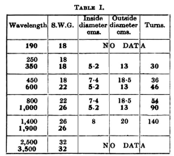 As the secondaries carry hardly any current, they may be wound with very fine wire such as 42 S.S.C.
 It may seem rather strange to use a crystal detector in these days of valves, but when it is remembered that with one valve used for dual amplification signals can be amplified 40 to 200 times, it will be seen that the valve is best employed as an amplifier.
|
Hits: 482 Replies: 0
Simultaneous High & Low Frequency Amplification
|
|
|
Gary Cowans
20.Sep.22 |
1
Simultaneous High & Low-Frequency Amplification By P. G. A. H. Voigt. Extracted from Wireless World December 10, 1921 Page 560-562 There are many circuits in which a valve will amplify both HF & LF currents simultaneously, thus obtaining with one valve an amplification for which two valves are usually used. This is a great advantage to those who have to fetch & pay for their filament current. I have tried many of these double amplification circuits, and those given are among the best. First, I shall explain the single valve double amplification circuit in Fig. 1, then I shall go on to the more complicated ones.
The HF oscillations are received on the aerial in the usual way by means of a variable inductance (shown fixed for clearness) and a variable condenser in parallel for long waves. The HF currents flow to the grid and to the filament through the blocking condenser, thus imposing an HF oscillation on the plate current. This oscillation produces oscillations in the tuned plate circuit similar to those in the aerial circuit but amplified. The oscillation here is passed to the crystal detector by means of the secondary winding, which should be very closely coupled to the primary, and wound or connected in the opposite direction as shown by arrows in the diagrams. Since the secondary only carries the crystal and reaction condenser current, it may be wound with very fine wire. This has the advantage of reducing capacity effects. The secondary may have more turns than the primary. The oscillation on reaching the crystal, causes it to pass a unidirectional current which will charge the blocking condenser between filament and earth. The voltage on this blocking condenser will flow to the grid & filament & vary the plate current without affecting the HF oscillation, producing doubly amplified signals in the telephones. Capacity reaction is used because in this instance it is as efficient magnetic but is much simpler to construct, as there is no need to make a variable coupling between any set of coils. The capacity reaction condenser should have a maximum capacity not exceeding 0.0001 microfarad and may be easily made as follows: - On a sheet of insulating material, a sheet of metal 5 cm by 5 cm is laid. This is covered by another sheet of insulating material, (i.e., 10 mil ebonite or waxed paper), and another sheet of metal 5 cm by 5 cm fitted with a flexible lead, and a long handle is laid on top so that the overlap can be varied. The minimum capacity must be small, and it should be possible to slide the sheets at least 5cm from one another. Better-looking condensers do not give better results but are more expensive. The principle of capacity reaction is quite simple. Suppose at a certain instant the wave makes the grid positive, then the plate current increases and makes the plate more negative, if the transformer secondary is connected in opposition to the primary the change of plate current will make the crystal and one side of the reaction condenser positive, the charge on this side of the condenser will attract an equal negative into the other side, leaving an equal positive charge free to add itself onto the initial charge, thus increasing it. In these circuits, a crystal not requiring a potentiometer, such as zincite, and bornite, or one of the artificial galena’s sold as permanite, rectarite, etc., must be used. With hard valves, the grid may be made slightly negative. This reduces valve damping, and sometimes gives an increase in signal strength.
The efficiency for wavelengths below 2, 000 metres can be considerably increased by shunting the resistance by a small condenser (0.002 µF) and putting in series a tuned circuit as shown in Fig. 4.
A further improvement in LF reaction is shown in Fig. 4. By putting a second condenser between filament and earth, separating the negative of HT and LT by a variable resistance having a maximum of 5,000 Ω, and making the voltage drop in this resistance by means of a potentiometer, LF reaction can be obtained which doubles or trebles the signal strength. Suppose the LF current made the first grid negative, then the first plate current would decrease and make the second grid positive, and the second plate current would increase to a much higher extent. The resultant through the HT and series resistance would be increased current. Hence the voltage drop along the resistance would increase and thus producing a higher negative potential on the first grid. A suitable resistance wire would probably be too fine for a slider, and therefore as many tapings as possible should be used. For the reaction resistance and the plate resistance, I advise one of the fine resistance wires, such as 48 S.S.C. Eureka, which has a resistance of 342 Ω per yard. About 150 to 200 yards would be required for a plate resistance. On long wavelengths, this method of amplification is difficult to work with, but for ordinary wavelengths the method is quiet and sensitive that I can receive the Dutch Concert (250 watts) on a four-foot square frame aerial indoors (top floor) with only 17 turns, using the circuit given in Fig. 4 in an open position in London.
Fig. 5 shows how transformers may be used for the inter-valve coupling; the HF transformer being tuned for preference.
The valve detector set will probably be very difficult to stabilise, and less time will be wasted in setting the crystal than fetching the extra current for a valve detector. Besides, the signals are loud enough with the crystal. See follow-up article Wireless World May 27, 1922. |
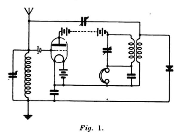
 Fig. 2 shows how a valve detector can be used instead of a crystal, but the second valve is much more useful if used in one of the two valve double amplification circuits shown in Figs. 3, 4, and 5.
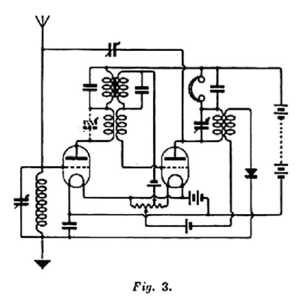 In Fig. 3 the second valve is coupled to the first by resistance coupling. The reaction condenser is connected to the plate of the second valve. This circuit works well at 600 metres, but like all resistance coupled amplifiers, its efficiency is low with short wavelengths.
 A switch is used to cut out the resistance condenser for “stand by” and the three tuned circuits used for “receive”. This circuit is wonderfully selective.
 Fig. 6 shows how a valve detector may be used with the two-valve circuit, the resistance coupling can be used between the valves instead of the coupling is shown, but is not so efficient, although much simpler.
End of forum contributions about this manufacturer/brand
| Data Compliance | More Information |