
History of the manufacturer
W-K (W.K.) Electric Co. (Winther-Kenosha); Kenosha, WI
Both will display your name after an officer has activated your content, and will be displayed under «Further details ...» plus the text also in the forum.
| Name: | W-K (W.K.) Electric Co. (Winther-Kenosha); Kenosha, WI (USA) |
| Brand: |
|
| Abbreviation: | wkelectric |
| Products: | Model types |
| Summary: |
W. K. Electric. Co., also W-K Electric Co. Brand / Trade name: Oriole Maker of triode TRF sets in the mid 1920's. The distinguishing common feature of all Oriole radios was the use of cathode followers driving step-up transformers instead of the usual grounded cathode stage with a tuned plate load. This alternative design was much more stable than the conventional approach without needing neutralization or damping. The Cathode Follower RF Amplifier design is described in US patent 1700393 by inventor Anthony Winther of Kenosha, Wisconsin, USA, the brother of company founder Martin Winther. |
| Founded: | 1923 |
| Closed: | 1927 |
| Production: | 1924 - 1927 |
| History: |
W-K Electric Co., aka Winther-Kenosha Company, Winther Motor Company, Winther Fire Engine and Truck Company. was founded by Martin Winther in 1923 as a reincorporation of his earlier companies in the automobile business. Radios were produced in the years from 1924 to 1927. These notes were collected from an article by Greg Hunolt in the October 2010 issue of Radio Age, the montly newsletter of MAARC, Mid-Atlantic Antique Radio Club. This article first appeared in WARCI News, the newsletter of the Wisconsin Antique Radio Club, Inc. |
| Country | Year | Name | 1st Tube | Notes |
|---|---|---|---|---|
| USA | 25 | Oriole 5 [5 tubes] | UX201A | Two dials (primary tuning control knobs) |
| USA | 25 | Oriole 6 [5 tubes] | UX201A | Two dials (primary tuning control knobs) |
| USA | 25 | Oriole 60 Special | UX201A | Two dials (primary tuning control knobs) |
| USA | 25 | Oriole 7 Special | UV201A | Two dials (primary tuning control knobs) |
| USA | 26 | Oriole 70 | ||
| USA | 26 | Oriole "The Canterbury" 75; ch= 7D [6 tubes] | Consolette model, transparent grain, solid black walnut cabinet. Bakelight panels, two ... | |
| USA | 26 | Oriole "The Mayfair" 78; ch= 7D [6 tubes] | Two-dial console. | |
| USA | 26 | Oriole 7D [125$; 5 tubes] | UX201A | Two dials (primary tuning control knobs) The earliest reference to the Oriole 7-D i... |
| USA | 26 | Oriole 7D [145$; 5 tubes] | UX201A | Two dials (primary tuning control knobs) |
| USA | 26 | Oriole 7D [210$; 5 tubes] | UX201A | Two dials (primary tuning control knobs) |
| USA | 25 | Oriole 8 Special | UX201A | Radio Collectors Guide says untuned Rf. That is incorrect, since the Radio has an Antenna-... |
| USA | 25 | Oriole 8 | UX201A | RF stage uses cathode follower with step-up transformer to achieve a net voltage gain o... |
Further details for this manufacturer by the members (rmfiorg):


|
Hits: 2231 Replies: 0
W-K Electric of Kenosha, by Greg Hunolt, WARCI, USA
|
|||||||||||||||||||||||||||||||||||||||||||||||||||||||||||||||||||||||||||||
|
Ernst Erb
09.Nov.13 |
1
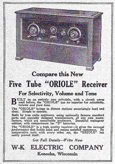
Greg Hunolt, President of the Wisconsin Antique Radio Club, Inc., which publishes "WARCI News", gave our member Alan Larsen the permission to publish his articles here at Radiomuseum.org - and Alan asked me to have a go for this article, sticky to the manufacturer page for W-K Electric of Kenosha. The article is from the issue May 2010. W-K Electric of Kenosha The Wisconsin Historical Society (WHS) website reports that Martin Winther incorporated the Winther Motor and Truck Company in December 1916 in Kenosha, Wisconsin, with his younger brother Anthony Winther working for him. The company shipped 500 Winther automobiles to Australia in 1917, but with the onset of World War I the company began making trucks and in 1918 received a contract from the U.S. Army to assemble four-wheel drive trucks. Following the war, Winther resumed production of Winther automobiles. In 1923 Martin Winther re-incorporated the company in Kenosha as the Winther Motor Company, and began using the trade name “Winther-Kenosha” for most of its products. The company was reorganized again in 1926 as the Kenosha Fire Engine and Truck Company, and in 1927 the company was sold. The Winther brothers went on with their careers in business. The WHS notes that although Martin and Anthony only attended school through the eighth grade, the two of them (separately or together) were granted patents for almost 300 car- and truck-related mechanical devices, including the first successful air conditioning system for Pullman railroad cars. See the WHS website for the full story of the Winther brothers’ career. Meanwhile, the W-K Electric Company of Kenosha advertised the “new Five Tube Oriole Receiver” in Radio Industry magazine in June, 1925, November 1925, and March 1926. See figure 1 for the June, 1925 advertisement.
Figure 1 – W-K Electric ad, Radio Industry, June 1925 W-K advertised the model 71 “The Warwick”, the model 75 “The Canterbury”, and “The Mayfair” receivers in Radio Retailing in October 1926 and Radio Broadcast and Popular Radio in November 1926. See figure 2 for the November, 1926, Radio Broadcast ad.
Figure 2 – Radio Broadcast, November 1926 Was there a connection between the Winther brothers of the Winther Motor Company of Kenosha and W-K Electric of Kenosha? The fact that the Winther brothers had adopted the Winther-Kenosha trade name – which one can imagine being abbreviated “W-K” – suggests a connection. But the clincher is patent number 1,700,393 for “Radio Frequency Amplification Circuits” issued to Anthony Winther of Kenosha, listed as the inventor. The patent application was filed on May 13, 1925, and the patent was granted on January 29, 1929. By that time the Winthers had sold the Winther company, and the patent was assigned to the All-American Mohawk Company of Chicago, Illinois, suggesting that Anthony Winther had sold the patent to Mohawk by that date.
Figure 3 – Winther Patent Title and Diagram See figure 3 for the title and diagram from the Winther patent. The Winther patent was for a vacuum tube radio frequency amplifier stage circuit that is now known as the “cathode follower”. In what was then the customary configuration, the amplifier stage would use plate loading, meaning that the ouput of the stage was produced across a load (e.g. either a transformer or resistor depending on the interstage coupling being used) in the tube’s plate circuit, i.e. between the plate and ground. In Winther’s design, the output load is between the tube’s cathode (which was the filament in tubes such as the 01A) and ground, and Winther’s schematic shows transformer coupled RF amplifier stages with the transformer primaries connected between the cathode and ground. The benefit of this approach, according to Winther, was improved efficiency and selectivity. (The term “cathode follower” derives from the fact that the output signal taken across a cathode load is in phase with, and hence “follows”, the input signal, while the output signal taken across a plate load would be 180 degrees out of phase with the input signal.) Antique Radio Classified, December 1989, carried a photograph of an Oriole model 7B receiver submitted by Robert Gordon of Muskego, Wisconsin, shown with permission here as figure 4.
Figure 4: W-K Electric "Oriole" 7B In his description of the set, Mr. Gordon noted the use of the cathode follower configuration in the two RF amplifier stages. His 7B schematic is reproduced here as figure 5.
Figure 5 – Oriole 7B Schematic Note the transformer coupling between RF stages in the filament (i.e. cathode) circuit consistent with the Winther patent diagram (figure 3, page 10 above). The 1925 ads for the Five Tube Oriole Receiver (see figure 1, page 9 above) proclaim that “built on an entirely new principle, with a circuit never used before, the Oriole has no superior for selectivity, volume, and pure tone”. The “Five Tube Oriole Receiver” in the ads appears to be the Model 7 (a 7B with a taller cabinet with a B battery compartment). The 1926 ads for the models 70, 75 and 78 tout the sets’ “amazing selectivity, delightful tone, and exceptional volume” pointing to their use of the “Trinum Circuit”. In December, 1926, Radio News magazine awarded the “Oriole Trinum” radio receiver (which appears to be the model 71 “Warwick”) its Radio New Laboratories Certificate of Merit. Figure 8 on the page 14 shows John Stroebel’s model 200 Oriole receiver. This set has an inside nameplate that says “Oriole Receiver Model 200, Serial 2164. Warning: The Trinum Circuit used on this receiver is patented. Any infringement will be prosecuted. W-K Electric Co., Kenosha, WI”. No patent number is cited, suggesting that when the radio was produced the patent application had been filed but not yet granted, which is consistent with the time frame for the Winther patent. Note that neither the Winther patent nor the 1925 ads mention the name “Trinum” for the circuit, but it seems safe to conclude that the “Trinum Circuit” referred to the cathode follower configuration described in the Winther patent and that W-K Electric was operated in Kenosha by Anthony and possibly Martin Winther in parallel with or as part of their Winther Motor Company. The table on the next page (taken from the 2010 edition of the Battery Set Compendium to be released in May or June 2010) lists receivers manufactured by W-K Electric according to the best information I have found so far. I believe the first two receivers, Models 5 and 6, were manufactured in 1924 – perhaps a stretch given that the earliest reference to them was in the portion of the 1925 Radio News Radio Set Directory published in the October 1925 issue. The last receivers are listed as 1927 models. Dale Boyce mentioned a booklet describing 1927-1928 models, but it seems most likely that W-K Electric ceased production at about the same time as the sale of Winthers’ Kenosha Fire Engine and Truck Company in 1927. Table: Radios Manufactured by W-K Electric (Battery Set Compendium 2010 edition):
Note EE, Radiomuseum: For 1924 we show now also Oriole 5 with 4 tubes and an Oriole 6 with 4 tubes. But I'm not sure if these new models are not doublets and we should put something into the notes. Also the tubes UX201A are in conflict (1925). If something turns up in a book, we have to show it - even if it has not been seen or was not made - to be really a reference work and not merely a catalogue. The Orion 90 might be the 90 Junior. Figures 6 and 7 show an Oriole Model 8 receiver, a four tube set, dating from about 1925.
Figure 10 – Oriole “junior” Model 90 Chassis Figures 9 and 10 above show an Oriole Model 90 “Junior”, a five tube receiver. Figure 11 below shows the chassis of the five tube Oriole Model 7B discussed above – note the similarity of the 7B to the 90.
Figure 11 – Oriole 7B Chassis A new design element on the 90’s front panel is the use of the small escutcheons around the tuning dials. Compare with the somewhat more elaborate escutcheon work on the Model 200, figure 8 above. Any information adding to or correcting the discussion of W-K Electric and their radios would be most welcome! “The Oriole Model 7B”, Robert Gordon, Antique Radio Classified, December 1989, p.8, copyright 1989 by John V. Terrey. Information from the article, including the photo of the Oriole 7B and its schematic are reprinted with permission from Antique Radio Classified (antiqueradio.com), P.O. Box 2, Carlisle, MA 01741 USA. John Stroebel provided photos of his Oriole 200, a copy of the patent, and the link to the WHS website. John noted that while he is currently living in Minneapolis his roots are in the Milwaukee area. He believes that his grandfather worked for W-K in the mid to late 20’s but lost his job in 1929 during the Great Depression.
Dale Boyce provided information about the W-K Electric Oriole sets in his collection. |
||||||||||||||||||||||||||||||||||||||||||||||||||||||||||||||||||||||||||||


|
Hits: 7437 Replies: 9
Cathode Follower RF Amp
|
|
|
Joe Sousa
04.Nov.10 |
1
Fellow Radiophiles, I have long held the supposition that the kathode follower topology might have been used as an RF amplifier in the 1920's using filamentary triodes. A recent article by Greg Hunolt first published in the May 2010 issue of the newsletter of the Wisconsin Antique Radio Club inc - WARCI, outlines the history of the Winther-Kenosha Electric company where the cathode follower RF amplifier was invented, patented in the USA with patent 1700393 and used in their entire line of 16 known radios of the mid 1920's.
The advantage of the cathode follower is that it is more stable than the grounded cathode amplifier with a plate load. The conventional grounded filamentary cathode stage has an inductive plate load that gets reflected at the grid as a negative conductance by the Miller capacitance feedback from plate to grid. It is this negative conductance that may completely cancel out all positive impedance losses in the grid circuit, and cause oscillations. Note that the cathode is loaded with a bifilar winding to carry the DC heating current, but acts as a single primary with respect to the tuned grid secondary. Felix Shaffhauser has worked out a very nice derivation of how the inductive plate load appears as a negative conductance at the grid. The cathode follower topic was previously addressed in Motorola cathode follower discovered. A simulated comparison of grounded cathode vs cathode follower (a.k.a. grounded plate) was also done previously. Regards, -Joe |
|
Joe Sousa
05.Nov.10 |
2
Fellow Radiophiles: The difficulty of using transformers instead of tubes to obtain voltage gain is that, while the impedances go up linearly with tube gain=gm*RL, the step-up transformer impedances go up with the square of the turns ratio. An early Audion has maximum unregenerated voltage gain under 10. This means that in a cathode follower RF amp, the cathode impedance is transformed by less than 100x by the step-up tank circuit, like from 1/1mS=1kOhm to 100kOhm. These turns ratios and impedances are realizable. Trying to duplicate the gain of 50 or more of a pentode IF stage with a follower and a step-up transformer is much more difficult. Perhaps the fixed frequency of a 455kHz IF makes this still feasible, but it seems impractical in a TRF stage that has to cover from 500kHz to 1700kHz. If gm=5mS and the cathode load impedance was 200 Ohms, a step up ratio of 100 would be needed to achieve the gain of 50, and the output impedance would be 2Meg. This is about 5x higher than the impedance of a few 100k I have seen in AM band 455kHz IF transformers that are resonated with 100pF caps and have 1.2mH of inductance. The 2Meg impedance would require a much higher L/C ration, with L on the order of 10mH and C on the order of 10pF, including self capacitance. Perhaps a high mu core material in a closed magnetic circuit core, such as a toroid or pot-core, would have yielded a 10mH inductance with less than 10pF of self capacitance. Even if the 2Meg IF transformer could be made, there is the further problem of heightened sensitivity to any negative conductance presented by the grid of the next stage, as might be the case, even if the next stage is also an inductance loaded cathode follower, with it's low, but non-zero reflected negative conductance.
One last possibility for the application of the cathode follower in later years, up to modern times, might have been in VHF or UHF front ends where the required gain is usually well under 20dB. This kind of single stage cathode follower also makes it easier to get some of the voltage gain simply by using a voltage step-up front end transformer with a reasonable ratio of 1:3. If the antenna impedance is 75 Ohms, the output impedance after 3x voltage transformation is 3*3*75Ω=675Ω. Another 1:3 transformer loading the cathode of a 10mS VHF UHF tube would have produced an output impedance of 3*3*100Ω=900Ω. The space charge causes high frequency loading at the grid in the range of 1kΩ to tens of KΩ, and sometimes this is the ultimate limiter for realizable gain in the VHF-UHF range. The follower topology should reduce this loading effect by the inherent bootstrapping by the cathode, and the small negative conductance that appears reflect at the grid for frequencies where the cathode load is inductive, may also help. This seems promising enough that it should be tried if an existing example can't be found. It is time to go scouring through the schematics of 1950's VHF TV boosters. Regards, -Joe
|
|
Jay Kinnard
09.Jul.18 |
3
It's interesting that this circuit is used in the Walbert Special Six and Gould radios that appear to predate the filing date of this patent.
|
|
Joe Sousa
13.Jul.18 |
4
Hello Jay, It would be great to see other cathode follower circuits. Can you please upload the schematics to the models? The filing date of 1925 predates the model years of 1927 and 1926 for the two radios you pointed out. Regards, -Joe
|
|
Jay Kinnard
13.Jul.18 |
5
Joe, You are correct. I was thinking that the patent was filed in 1927. The Gould and Walbert Special Six are the same radio except for the name. The Special Six appears to be the only radio by Walbert with the cathode follower RF amplifiers. I have only a partial hand drawn schematic and pictures of the wiring from an Ebay sale. The RF circuits are identical to the patent schematic except for the addition of a filament rheostat and a B+ to A+ bypass capacitor. I have been told that some Cascade models by Nunn-Landon also use the cathode follower circuit. Those are probably associated with Winther-Kenosha since the company is located in Winsconsin. I don't have any schematics for those radios but will check with other collectors. Since Walbert was a circuit innovator, it seems probable that they developed the cathode follower circuit independent of Winther. I don't know of any connection between the companies and am not aware of any litigation involving the Winther patent. Jay |
|
Dietmar Rudolph † 6.1.22
14.Jul.18 |
6
In "Funk-Bastler", a report by Carl Lübben is given about a new type of receiving scheme on pp. 289 / 290.
Lübben reports from an Englishman, Johnston, who published this new type of receiving circuit. You will find the original text which is in German. However the schemes nevertheless will be clear, I hope.
No further information is given by Lübben. The volume of "Funk-Baster" had 35 numbers in 1924. So this information was given in summer 1924. Probably, the invention of Johnston was prior to the Winther-Kenosha Electric company. Regards, Dietmar |
|
Dietmar Rudolph † 6.1.22
14.Jul.18 |
7
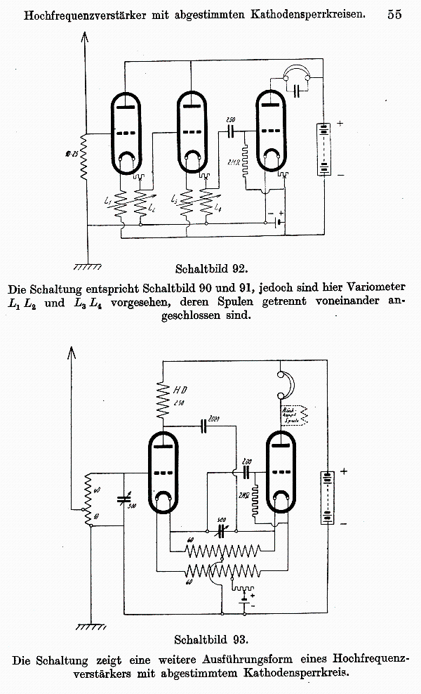
Additionally, in "Singelmann, M.: Störbefreiung in der Drahtlosen Nachrichtentechnik, Meusser, 1926" which is volume 7 of the "Lübben: Hochfrequenz-Technik" series, in chapter 6 some additional cathode follower RF amplifiers are presented.
Singelmann gives the sources for: schematics 90 to 92: Wir. Weekly 4, No. 9, 277 schematics 93 & 94: Mod. Wir. 3, No. 4, 367 Regards, Dietmar |
|
Jay Kinnard
15.Jul.18 |
8
Dietmar, Do you know of any European radios that used the cathode follower circuit? Jay |
|
Dietmar Rudolph † 6.1.22
17.Jul.18 |
9
The schematics No 90 to 94 in post #7 are much too faint because the prints in the book are really poor. Joe Sousa was so kind to help improving the schematics: "I improved the scans with Photoshop. A Gauss filter and enhancing contrast for several times has been done. The Gauss filter parameter is 1-2 pixels. In this way the thin lines will become thicker."
Regards, Dietmar
|
|
Joe Sousa
08.Aug.20 |
10
The circuits presented above by Lübben in Funkbastler in 1924 and from the Singlemann book in 1926 are worthy of further comment and contrast with the approach that was successfully pursued by Winther-Kenosha. To that end I offer my translation of the these texts in blue: Funk Bastler, my translation of text from Lübben about Johnston. An Englishman has discovered a new circuit in which self-oscillation cannot occur. The basic idea of this new circuit is that the oscillating circuit in the anode has been moved to the cathode. The alternating potential in the anode circuit is thus moved the cathode, but with such a (opposite) phase, that no self-oscillation occurs. Fig. 3 (correction of Abb. 2) shows the simple grid leak detector with this new circuit configuration. A disadvantage of this circuit is that the filament battery now has a high-frequency alternating potential and must be well isolated. A further disadvantage is that a set with multiple stages requires a separate battery for each cathode stage. On the other hand, one advantage is that the grid of each succeeding stage can be directly connected to the cathode of the previous stage, thus avoiding a coupling capacitor that would be required to block the high voltage potential from the anode of one stage to the grid of the next in a conventional plate loaded circuit. A multi-stage circuit (two high-frequency stages and a grid leak detector stage) in the new configuration is shown in Fig. 3. With this new circuit, it is possible to use a common filament battery for all tubes if the tank circuits in the cathode (corrected from anode) are separated for each filament battery terminal. The circuit shown in Fig. 4 implements this approach, or the simpler circuit of Fig. 5, in which both sides are the coils of a variometer. For practical experiments with these circuits it should be mentioned that one should not be surprised if one has a much lower volume than with other conventional circuits. It should be noted, however, that this new circuit lacks the intrinsic feedback that is always present in other circuits. A comparison (with conventional circuits) is only possible when external overall feedback has been applied to the maximum in each case. The external overall feedback can be applied any known manner to the new circuits. My translation of the text by Singelmann 6. High frequency amplifiers with tuned notch tank circuits at the cathode. Compared to configurations with tuned anode tank circuits, the configurations presented here have the great advantage of absolute stability. Any number of stages can be connected one after the other without a tendency to oscillate. In order to achieve a reduction in attenuation, a special feedback must therefore be provided. The stability arises from the fact that the potential oscillations at point A (Fig. 4) and the corresponding oscillations at the have the same sign, so the signals fed back by the grid-anode [cathode?] capacitance do not mutually reinforce each other, as in the case with resonant anode tank circuits (cf. P. 41). Other advantages over circuits with tuned anode tanks are good selectivity without difficult adjustment and a saving of individual parts per amplifier stage. It should be noted that the filament batteries must be well insulated because they have a potential to earth. The filament wires must be as short as possible. ---- page 54 --- High-frequency amplifier with tuned cathode notch circuits. The circuit shows one of the simplest embodiments of a high frequency amplifier with tuned cathode notch circuits. Circuit diagram 91 The circuit is a further embodiment according to circuit diagram 90. In parallel to the coils Lt and Lt, variable capacitors of 500 pF(?) can also be connected. The coils mentioned must then have 76 turns for the usual radio wave range. --- page 55 --- High-frequency amplifier with tuned cathode notch circuits. Circuit diagram 92 The circuit corresponds to circuit diagram 90 and 91, but here variometers L1L2 and L3L4 are provided, the coils of which are connected separately from one another. Circuit diagram 93 The circuit shows a further embodiment of a high-frequency amplifier with a tuned cathode notch. --- page 56 --- High-frequency amplifier with tuned cathode notch circuits. Circuit diagram 94 The circuit shows an embodiment of circuit diagram 93 for three tubes. One odd point in the Lübben text in Fünk Bastler is the reference to the parallel tank circuits at the cathodes as notch filters (Sperrkreisen) instead of bandpass filters. A parallel tank circuit at the cathode works as a notch filter if the signal output is taken from the plate. The response of the signal taken from the cathode is clearly a bandpass; not a notch. As hinted at in the original text, the gain for each stage is less than one for this approach, unless some form of regenerative feedback is used to boost the overall system gain. This is very clear for the single stage illustration in the first figure, figure 4 (Abb. 4) in the Lübben text. This circuit can provide power gain and reasonable selectivity with reasonably well chosen L and C values. The voltage gain is limited to 1-1/mu (mu is the intrinsic voltage gain of the tube from grid to plate), which for a mu=7, works out to nearly 0.9 with an infinite impedance cathode load. For maximum power gain, the tank impedance at resonance should match the cathode impedance, which is on the order of 1/gm=2k (gm is the transconductance of the tube). If the tank can be counted on for a Q=50, the reactance of L and C at 1MHz must both be 6.4uH and 4.0nF with a reactance of 40Ω=2000Ω/50. These values are well outside the values hinted at later in the schematics (C=500pF). With my calculated values, the power gain is maximized with a voltage gain a little under 0.5 (because the unloaded gain is limited to 0.9; not 1) and the net Q of the tank under load is only 25. A lower impedance tank, with higher C and lower L would give a net higher Q and selectivity, but at the expense of lower voltage and power gain. The W-K circuit realizes maximum power gain with an impedance matched cathode load, but also realizes a significant voltage gain between 2x and 5x depending on the step-up tuned transformer configuration. The polarity of the battery connection for the cathode follower stages in figure 4 (Abb. 4) in the Funk Bastler text is reversed. In the configuration shown in the drawing will bias the grid of the next stage strongly positively, thus making it very conductive, which attenuates the signal driven to it. But it is a simple fix to swap the filament polarity of the cathode connections. Figure 90 (Schaltbild 90) shows the simplest configuration hinted at in the text, with two cathode follower stages and global feedback with a tickler coil coupled to the antenna tank. The overall net gain is going to be less than if the two cathode follower stages were eliminated to turn the circuit into a conventional regenerative detector. However, the selectivity should be substantially higher due to the three tuned tank circuits in the signal path. The last section in the article about the W-K Oriole model 7-B explores the advantages of global regeneration over several tank circuits. Figure 91 (Schaltbild 91) shows the tank circuit shorted out with a 20Ω resistor in series with the tube filament resistance, which is in the range of 4-20Ω, depending on tube type. This resistances short out the tuned tanks and any possibility for passing any signal. Figure 92 (Schaltbild 92) replaces the tuned tanks at the cathodes with variable inductances. At best, with large inductance values, the two cathode follower stages have a combined voltage gain of 0.8=0.9*0.9. As shown the circuit presents no explicit resonant circuit. But the version in the Lübben article above in figure 5 (Abb. 5) shows a tuned antenna circuit. Figure 93 (Schaltbild 93) The operation of this circuit is not obvious with the explicit feedforward or feedback path from the plate of the first tube to the cathode of the second tube. This is plausibly a cathode follower circuit with regenerative feedback. Some experimentation with circuit simulation with LTspice could reveal the characterstics of the circuit. Figure 94 (Schaltbild 94) This is the most intriguing circuit in the collection, in that a tuned tank circuit with a grounded centertap is driven on both ends by the cathode and by the plate. The plates show inductor loads (inductors are drawn with zigzag lines and resistors are drawn with square pattern) which are coupled with 2000(pF?) to the opposite end of the tank. If this circuit manages to not oscillate, it may have interesting characterisistics. But the connection of the third stage cathode, which is the grid-leak detector, would badly dampen the tank of the second stage. Perhaps one or more of the circuits in Singelmann managed to work reasonably, but that is not obvious. It is also clear that there were problems in the writing about the circuits. The Funk Bastler text by Lüben has fewer mistakes. As compared to the successful W-K circuit, one can wonder if Johnston developed his circuit further, he might have come to a similar solution that actually outperformed conventional sets, as the W-K circuit does. Regards, -Joe |


 Many thanks to Joe Sousa for his kind help!
End of forum contributions about this manufacturer/brand
| Data Compliance | More Information |