
History of the manufacturer
Titus Konteschweller, Dr. Titus; Paris
Both will display your name after an officer has activated your content, and will be displayed under «Further details ...» plus the text also in the forum.
| Name: | Titus Konteschweller, Dr. Titus; Paris (F) |
| Abbreviation: | titus-kont |
| Products: | Model types |
| Summary: |
Dr. Titus Konteschweller Marque : Dr. Titus ou Titus |
| Founded: | 1923 |
| Production: | 1923 - |
| History: |
| Country | Year | Name | 1st Tube | Notes |
|---|---|---|---|---|
| F | 24 | Normal | Montage super-réaction, Modèle normal. Montage super-réaction mod&... | |
| F | 23/24 | Ordinaire | TM | Montage super-réaction modèle ordinaire. See also in: P. HEMARDINQUER ... |
| F | 24 | Valise "Le Camping" | Montage portable à superréaction, cadre et écouteurs compris. | |
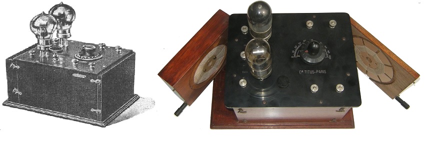
| F | 25 | Coffret á deux lampes | Poste superréaction avec deux lampes protégées en coffret - montage g... | |
| F | 27 | Récepteur portable | Montage superréaction portable à cadre et écouteurs inclus. | |
| F | 28 | Coffret Metalique | ||
| F | 13 | Ordinaire - Réplique | 2Ж27Л | This is a replica of DR. TITUS model "Ordinaire" build by members of "Pro-R... |
| F | 26 | Coffret á trois lampes "Ultra-Réaction" | Poste Titus ultra-réaction avec trois lampes en coffret. Selfs interchangeables ... | |
| F | 24 | Universel | W_Metal | Montage super-réaction modèle universel. See also in: P. HEMARDINQ... |
| F | 30 | C 4.3 |
Further details for this manufacturer by the members (rmfiorg):


|
Hits: 4191 Replies: 0
TITUS KONTESCHWELLER
|
|
|
Pitagora-Petru Schorsch
02.Jan.17 |
1
TITUS KONTESCHWELLER Brief Historical Background Titus Konteschweller was born at the end of the 1890s, elder son of the pharmacist Eduard Konteschweller. After graduating the high school in Craiova (his native town in south-east Romania) he leaves for Paris to study medicine. Taking his doctor degree he settles in Paris as a physician, already known since 1918 in French medical circles as the one who introduced the word “pyreotherapy” into the medical language. At the beginning of the twenties his younger brother Mihail Konteschweller arrives also in Paris to study electrical engineering. At the beginning of the broadcasting era in France, as the most part of the young generation, the two brothers develop a passion for radio-technique. The 27th of June 1922, Mr. Edwin Howard Armstrong applies and is attributed (in less than a month), the 25th of July the patent for super-regeneration. (“Signaling system", US patent 1424065) A few months later, on the 14th of November 1922, Mr. Edwin Howard Armstrong holds in Paris a public conference followed by a practical demonstration, introducing the Super-Regeneration to the French public, at the invitation of the French amateurs “Les Amis de la T.S.F.” The conference and following demonstration triggers the enthusiasm of many French amateurs who start experimenting with the new principle. However, (as stated in the newspapers of the time) the circuit being not so easy to understand and to master, the big majority soon looses interest, and after a while, only a very few (the real “connoisseurs”), continue to advocate and use the super-regeneration. Most probably the Konteschweller brothers attended the conference and surely Titus obtained a licence to manufacture super-regenerative sets in France. In the fall of 1923 Dr. Titus Konteschweller establishes the company DR. TITUS PARIS entirely dedicated to manufacturing super-regenerative radio sets. The Company “DR. TITUS” Disclaimer: In this presentation we do not intend to negate or minimize the contribution of the younger brother, Mihail Konteschweller, to the achievements of the company. We are convinced that Mihail’s training as an electrical engineer brought a major contribution to the professionalism of the enterprise. But for obvious reasons Konteschweller brothers chose Titus as the leading figure in Paris. As a consequence, all the technical articles and advertising from the French newspapers of that time, which guided us in writing this text, are mentioning him alone. We do believe we respect their choice by doing the same. The reader will know that we mean both Titus and Mihail Konteschweller although we mention only the first, in order to stay true to our sources of information. Dr. Titus Konteschweller belonged to those very few who really mastered the theory and the practice of the super-regeneration. He is (to our knowledge) the only “Radio Amateur” of that era that reached the status of “Radio Manufacturer” becoming the best known manufacturer for super-regenerative radio sets in France.
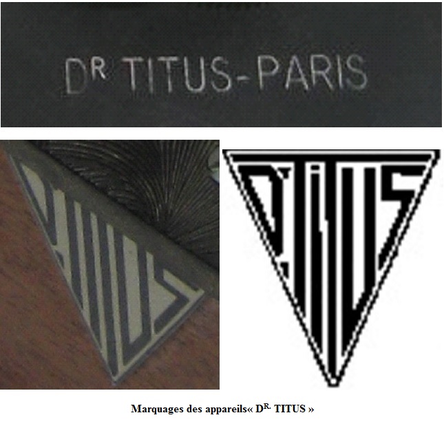
Markings and logo on DR. TITUS’ sets The markings on the manufactured sets vary from plain engravings “DR. TITUS-PARIS” on the panels to a logo containing styled in a triangle the words “DR. TITUS”. Articles in technical papers and advertising published in technical magazines prove the existence, between 1923 and 1930, of the company “DR TITUS”, specialized in manufacturing only super-regenerative receivers belonging to Dr. Titus Konteschweller rue Wattignies, Nr. 69, Paris XII:
Advertising published January 1924 in the magazine “La Science et la Vie” Circuit Diagrams of “DR. TITUS’” First Set (The Basic Circuit Diagram) The circuit diagram of the first set (the basic circuit diagram) is to be found, in the magazine “La Nature” from 1925 in an article by P. Hemardinquer with the legend: ”Super regenerative circuit with 2 valves, the first detector, the second oscillator using the variation of the positive resistance (DR. Titus’ circuit)”
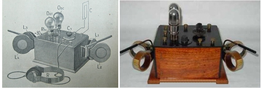
The circuit diagram “Dr. Titus” from “La Nature” 1925. The radio waves collected by the loop antenna and selected by the variable capacitor C1 are sent through the detection group R1 C2 on the grid of the first valve - the super-regenerative detector (Dét.). The coils L1 and L2 respectively in the grid and plate circuit of the first tube are magnetically coupled to produce strong regeneration. The headphones (R) with the parallel capacity (C3) close the plate circuit to the positive pole of a plate (B) battery delivering 80 to 120 V. The filament is heated through the rheostat Rh1 (having also the role of a circuit breaker), from a 4 ÷ 5 V storage (A) battery. The second valve- “Oscil.” together with the grid resonant circuit L3 C4 and the plate regeneration coil L4 (“tickler”) form the quenching oscillator. It produces the low frequency signal (8 kHz) which is applied on the grid of the first tube before the detection (grid leak) circuit (R1 C2) interrupting periodically the exponential growth of oscillation in the super-regenerative detector. Both tubes use the same plate and filament batteries and the same rheostat. There are two (slightly antagonistic) principles governing the performance of super-regenerative receivers: 1. The gain is inverse proportional with the difference between the received and quenching frequency. That is, for maximum gain one should choose the lowest quenching frequency one can afford. 2. The Nyquist-Shannon principle shows that for retrieval without distortion of a signal, the theoretical lower limit of the sampling frequency should be (at least) the double of the highest frequency in signal’s spectrum. Nowadays one chooses the quenching/sampling frequency slightly above the hearing range using mostly a self-blocking quenching oscillator working on the same active device as the super-regenerative detector. That makes super-regeneration usable only with short and ultra short waves. On the twenties, with the available loudspeakers, using separate sinusoidal quenching oscillators one could afford to lower the quenching frequency towards 8 – 12 kHz without punishing too much the ears of the audience. Titus Konteschweller choosing a quenching frequency of 8 kHz (sometimes slightly lower) succeeds in obtaining with only two valves and small loop antennas, loudspeaker level from remote transmitters. Edwin Howard Armstrong using quenching on 10 – 12 kHz for his demonstration set in 1922 had to add an AF stage to reach loudspeaker level:
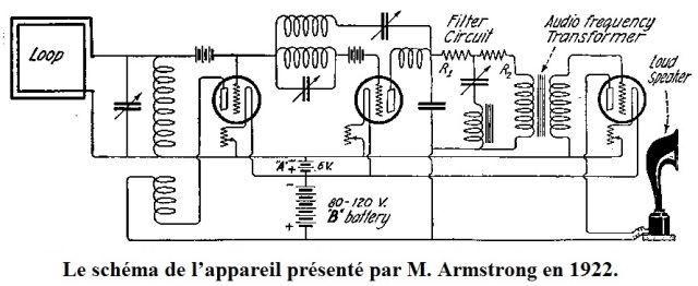
Circuit diagram of Mr. Armstrong’s demonstration set 1922 The Super-Modulator Trying permanently to improve the quality of his sets, Titus Konteschweller invents and publishes the concept “Super-Modulator” combining frequency change with super-regeneration:
The Super-Modulator DR. TITUS circuit diagram and the experimental set-up. The first two valves are (respectively) the modulator (A) and the local oscillator (B) of a frequency convertor (Ultradyn) transforming the incoming long or medium waves in an intermediate frequency, higher as the one received, somewhere in short waves’ range. The last two valves are the super-regenerative detector (C) and quenching oscillator (D). The resulting set combines on all wavelengths the characteristic high gain of the super-regeneration with super-heterodyne selectivity and higher fidelity (due to the increased sampling frequency). According to our information, the super-modulator (due probably to the lack of proper licenses) has not reached production stage. Titus’ Ultra-Regeneration Titus Konteschweller adds another valve as tuned radiofrequency amplifier in the regeneration loop of the super-regenerative detector which substantially increases gain and selectivity. Actually he named this new receiver “Ultra-Regeneration”, unaware the name was already used by Lee De Forest. We choose to rename it Titus’ Ultra-Regeneration to avoid confusion.
The tubes “A” and “C” are (respectively) the super-regenerative detector and the sampling oscillator. The “B” tube is the tuned radiofrequency amplifier meant to improve the gain and selectivity. Single-valve receiver Using a double-grid valve (spatial charge grid valve = bigrille)
Single valve receiver super-regenerative set using Numans-Roosenstein’s oscillator The radio waves collected by the loop antenna (in fact a 15 cm diameter “Gabion” coil) and selected by the variable capacitor 0.5/1000 µF are sent through the coupling capacitor 0.2/1000 µF on the second grid of the valve, the resistor 2 [M]Ω providing the correct bias. The current of the first grid is injected (by the direct connection specific to the Numans-Roosenstein oscillator) into the tuned input circuit and produces regeneration. The input circuit oscillates on the received frequency. The inductance L tuned by its parallel capacitor C (2/1000 µF) on a lower frequency constitutes the quenching oscillator, cutting regularly the input circuit oscillations. like in all super regenerative receivers. The headphones with the parallel capacitor (10/1000 µF) are closing the plate circuit to the positive pole of a 16 - 24 VDC battery. The filament is heated by a 4 V accumulator through the 30 ω [30 Ω] rheostat provided also with a circuit breaker. Small modifications in the basic circuit diagram Some minor modifications appear with the passing of the years: In 1926 Mihail Konteschweller (Titus’ younger brother) publishes in Romania in the magazine “Radiofonia” (The Radiophony) the basic circuit diagram. One notices an extra capacitor C5 in parallel with the quenching oscillator tickler L4:
Circuit diagram published in 1926 in Romania In order to gain more space inside a portable set in 1927, L3 and L4 are wound together on a single former, the control of the quenching oscillator is made by a second rheostat and by varying the taps on the anode battery. Also because the audition was made in headphones, a filtering LC was installed in parallel to diminish the super-regenerative whistle.
Circuit diagram published in 1927 in Radio News Dr. TITUS’ Receiver Sets Disclaimer: We were not able to find a printed catalogue or a reliable list containing all the types of sets manufactured by “DR. TITUS”. We can only bring to your attention our attempt to systemize information gathered from articles and advertisements published in the newspapers and magazines of the time. We also used information provided by the actual collectors or collector’s associations, therefore the dates of manufacturing and release on the market, could not always be set accurately. (There are still collectors “over-aging” their collected items whether knowingly or not.)
If somebody has this catalogue or knows where it could be found, please give us notice! STATIONARY SETS “Classical” Design 1924 Single-valve receiver Super-regenerative set equipped with a double-grid valve using Numans-Roosenstein’s oscillator. Only one interchangeable coil used as loop antenna. Theoretically it could receive all wavelengths. (Only by changing the coil)
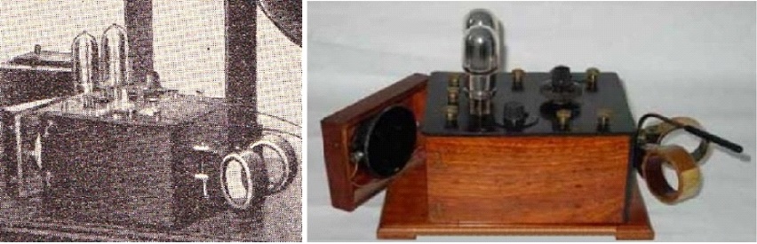
1923 “Ordinaire”(The first set) The first set using the basic circuit diagram. L2 and L4 are in the lateral flaps. It receives only middle waves. :
“Ordinaire” Only MW. The first set DR. TITUS 1923 As stated in the later advertising it will be also manufactured in the following years, and in order to be distinguished from the newer models it is named “modèle Ordinaire” 1924 “Normal” The set is using the basic circuit diagram. L4 is in the lateral flap, L2 is movable and both L1 and L2 interchangeable. Theoretically it could receive all wavelengths.
“Normal”. All Wavelengths DR. TITUS 1924 In the later advertising it will be named “modèle Normal” in order to be distinguished from the other models. 1924 “Universell” The set is using the basic circuit diagram. L1, L2, L3 and L4 are interchangeable. L2 and L4 are movable. It receives all wavelengths and allows the changing of the quenching frequency.
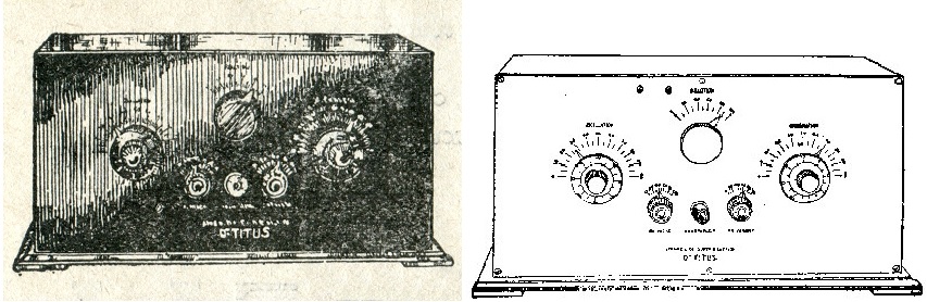
“Universell”. All Wavelengths. Variable Quenching. DR. TITUS 1924 In advertising it is named “modèle Universell” in order to be distinguished from the other models. “Cabinet” Design Around 1925 -26 the French market is invaded by American receivers bringing a new design. All components are “hidden” inside a cabinet, only the controls and the binding posts are visible. Titus Konteschweller starts putting his receivers in cabinets. 1926 “Coffret à deux lampes” (Cabinet with Two Valves) The set is using the basic circuit diagram.
1926 Coffret à trois lampes. (Cabinet with Three Valves) The set is using the Titus’ Ultra-Regeneration circuit diagram.
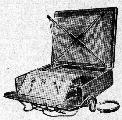
PORTABLE SETS 1924 “Camping” The set is using the basic circuit diagram.
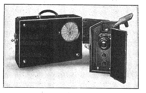
DR. TITUS’ Camping 1924. A suitcase measuring 14 X 35 X 50 cm contains everything: loop antenna, receiver batteries and headphones. (Together with the storage (A) battery it weighs 10 - 11 kg) The set enjoys a big public success. (Too big maybe.) It is said that the first prototype displayed at 1924 “Foire de Paris” (the Paris Fair in 1924) disappeared in broad daylight from the stand it was exhibited! 1927 “Portable” The set is using the circuit diagram published in 1927 in Radio News. Lighter and smaller than “Camping”, the suitcase containing all the peripherals measures only 29 X 25 X 13 cm, and weighs 4.5 kg. It is exhibited with success at “Salon TSF 1927” then it becomes the “Grand Prix” at Liège 1927 and finally wins the first prize at the super-regenerative receiver contest organized by the New York magazine “Radio News” in the same year.
Best regards, Leverkusen 18.01.2017 Pitagora Schorsch Attachments
|


|
Hits: 1877 Replies: 0
“DR. TITUS” MODELS
|
|
|
Pitagora-Petru Schorsch
07.Jan.17 |
1
“DR. TITUS” MODELS Attempt to systemize and name the receivers produced by DR. TITUS - PARIS
The coherent information about the receivers Titus Konteschweller produced and sold is scarce. In order to systemize and correctly name his radio sets we definitely lack the original printed catalogue (so many times advertised in the papers):
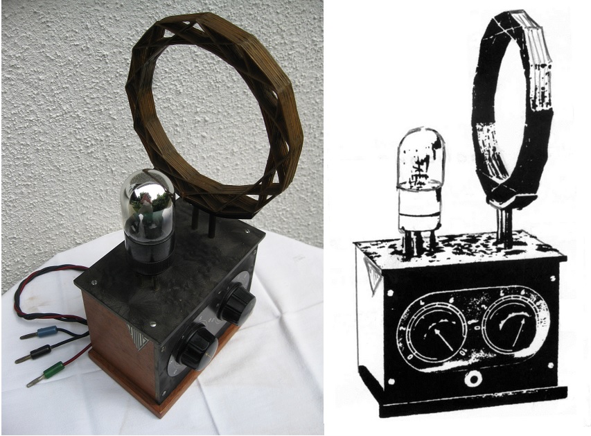
If somebody has this catalogue or knows where it could be found, please give us notice! We had to gather information from the technical books printed in that period and from the publicity printed in the technical magazines. The advertisement documenting the existence of the first DR. TITUS model appeared in the January 1924 issue of the magazine “La Science et la Vie” (The Science and the Life):
Here we are shown the picture/drawing of the first model, we find out it weights two kilograms, the physical dimensions: 20 X 17 X 17 cm, that it employs 2 valves, (one can see they are T.M.s), that on a 50 cm Loop–Antenna it can receive in loudspeaker all existent MW broadcasting and even LW broadcasting at great distance, but on harmonics. The set was exposed at “Concours Lepine” (Lepine Contest) and at the “Physics Exhibition” and costs – 500 francs. Let’s now compare this information with what we can find in the second piece of advertising printed also in “La Science et la Vie” but in the May 1924 issue: I uploaded it with the first model because of the picture, but the text thoroughly analysed will give us information about the first and further 3 models: Although the picture shows TM valves, the text states:
(Suppression of accumulators through usage of low consumption valves.) That means, that before May 1924 the basic circuit diagram was adapted to low consumption valves. Further on:
Here we find out that, “Concours Lepine” and “Physics Exhibition” (both mentioned in the first ad) took place in 1923. Now we can be absolutely sure that the first DR.TITUS model was manufactured starting 1923. Further on the page we find the first quotation:
(The “Modèle Universel” receiving from 180 to 3 000 m (on fundamental wave) costs “naked” 800 fr.) Then the second:
(The “Modèle Ordinaire” receiving amateurs [200 m] Broadcasting [MW] and LW on harmonics costs “naked” 550 fr.)
(Both “Universel” and “Ordinaire” have a mahogany case, hand polished, 23 X 13 X 15 cm) It is obvious that he performances quoted with the “Ordinaire” model, match the performances quoted with the first model: Having only one pair of MW coils (affixed in the lateral flaps) it can receive LW only on harmonics. This is why I suggest naming this model: (Please click here)= Modèle Ordinaire The “Universel” must have interchangeable coils to be able to receive a fundamental wave up to 3 000 m. And this is why I suggest naming this model: (Please click here)= Modèle Universel Looking at the picture you will notice that this model has two pairs of interchangeable and movable coils. Precisely, not only the tuning coils are interchangeable but also the quenching frequency ones. That makes this set more “universal” than any other model DR. TITUS manufactured. Let me briefly explain: When receiving lower frequencies (LW) the performance of the super-regenerative detector diminishes. That can be compensated only by diminishing the quenching frequency and that is exactly what Titus Konteschweller did: Mr. Edwin Howard Armstrong in 1922 receiving broadcast band (MW) with a quenching frequency of 10 – 12 kHz wasn’t able to reach loudspeaker level without an AF amplifier as a third stage. Titus Konteschweller by daring to lower the quenching frequency to 8 kHz (and even slightly under) succeeded to obtain loudspeaker level with only two valves on MW and tolerable performance on LW. It is also true that the European valves of that period had slightly better performances than the American ones. Building the “Modèle Universel”, Titus Konteschweller enabled the user to lower even more (if he so chooses) the quenching frequency (by changing the respective coils), gaining performance in spite of increased distortion on the high frequency sounds. I take it that the limited frequency range of the loudspeakers of that period helped a lot this distortion, to pass unnoticed. The model with one flap and one pair of interchangeable coils is named “il apparechio normale” in an Italian paper scanned and uploaded by Sig. Orazio D’Amico: I put some more light and contrast and I cropped the picture a bit in order to better illustrate the set:
This should definitely explain why I suggest naming this model: (Please click here)= Modèle Normale
To be continued. Best regards Pitagora Schorsch
|


|
Hits: 1737 Replies: 0
KONTESCHWELLER MIHAIL
|
|
|
Pitagora-Petru Schorsch
03.Jan.17 |
1
KONTESCHWELLER MIHAIL A l’occasion de sa 10-eme anniversaire, l’« Association néerlandaise de radiotélégraphie » publie un ouvrage commémoratif « GEDENKBOEK N.V.V.R. 1916 MAART 1926 ». Parmi les sommités invités a écrire un article se trouve aussi Konteschweller Mihail (en Français Michel) qui présente la super-modulation et l’ultra-réaction, montages récents, établis avec son frère ainé Konteschweller Titus.
L’article, a été écrit á Bucarest ou Mihail résida en 1926. Konteschweller Mihail après avoir fini ses études, et aussi d’aider son frère ainé Titus à démarrer l’entreprise « DR. TITUS » a Paris, retourne en Roumanie, a Bucarest ou il poursuit sa propre carrière. Il est resté cependant en permanent contact avec son frère, en écrivant des articles de présentation pour les superréactions « DR. TITUS »(comme on l’ait vu plus haut), et en titre du représentant « DR. TITUS » pour la Roumanie. Voila une réclame publiée dans la revue « Radiofonia » (La Radiophonie) N° 4 du 1er Décembre 1925 :
En Français : SANS ANTENNE !! Admirables réceptions sur cadre à millier et millier de kilomètres Voila les résultats qu’on obtient constamment et facilement, avec les plus modernes appareils sur le marché : La Super-Réaction et l’Ultra-Réaction FABRIQUEES PAR Dr. TITUS KONTESCHWELLER 69 Rue de Wattignies, PARIS III-e INFORMATIONS peuvent être demandées a l’Ingénieur M. Konteschweller 45 Rue Popa Tatu BUCAREST
Et encore une publiée dans « Radiofonia » (La Radiophonie) N° 5-6 du 1er Janvier 1926 :
En Français : SEULEMENT A DEUX LAMPES VOUS POURRIEZ ENTENDRE SUR CADRE INTERIEUR LES POSTES EUROPEENES « EN HAUT-PARLEUR » --- LA SUPER REACTION et L’ULTRA REACTION --- CONSTITUENT LE DERNIER MOT DE LA TECHNIQUE RADIOPHONIQUE LES APPAREILS SONT CONSTRUITS PAR Dr. TITUS KONTESCHWELLER - 69 Rue de Wattignies, PARIS X-e INFORMATIONS PEUVENT ETRE DEMANDEES A L’INGENIEUR M. KONTESCHWELLER - 45 RUE POPA TATU - BUCAREST J’ignore pourquoi dans les réclames postée plus haut, 69 Rue de Wattignies (ou se trouvait l’Entreprise « DR. TITUS ») est localisée dans le III-eme ou dans le X-eme arrondissement. Je suppose une faute d’imprimerie. J’ai vérifié moi-même : sur « Google Maps » 69 Rue de Wattignies à Paris se trouve dans le XII-eme arrondissement. Dans toutes les réclames imprimées en France le siège de l’Entreprise « DR. TITUS » est localisé correctement dans le XII-eme arrondissement. Bien cordialement, Pitagora Schorsch Attachments
|


End of forum contributions about this manufacturer/brand
| Data Compliance | More Information |