- Country
- Germany
- Manufacturer / Brand
- Telefunken Deutschland (TFK), (Gesellschaft für drahtlose Telegraphie Telefunken mbH
- Year
- 1945/1946
- Category
- Broadcast Receiver - or past WW2 Tuner
- Radiomuseum.org ID
- 4138


Click on the schematic thumbnail to request the schematic as a free document.
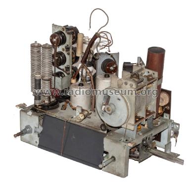
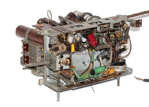
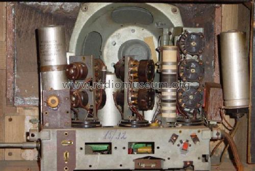
- Number of Tubes
- 7
- Number of Transistors
- Semiconductors
- Selengleichrichter Selengleichrichter
- Main principle
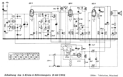
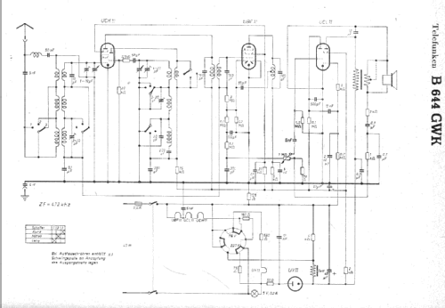
- Superheterodyne (common); ZF/IF 472 kHz
- Tuned circuits
- 5 AM circuit(s)
- Wave bands
- Broadcast, Long Wave and Short Wave.
- Power type and voltage
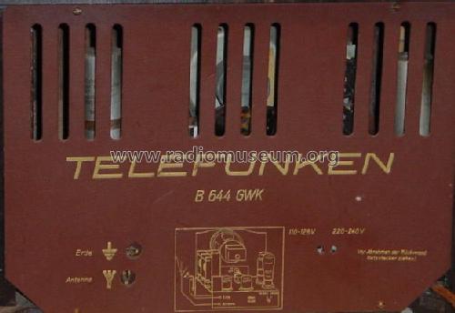
- AC/DC-set / 118/220 Volt
- Loudspeaker
- Electro Magnetic Dynamic LS (moving-coil with field excitation coil)
- Material
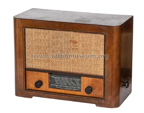
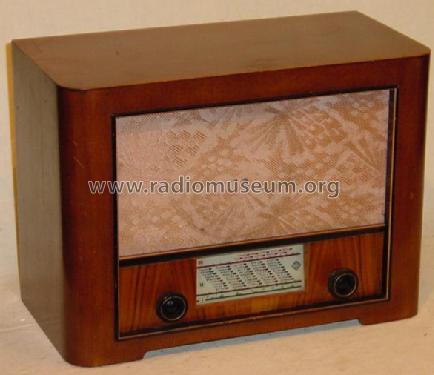
- Wooden case
- from Radiomuseum.org
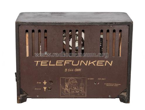
- Model: B644GWK - Telefunken Deutschland TFK,
- Shape
- Tablemodel, low profile (big size).
- Notes
-
B = Fertigung aus Dachau
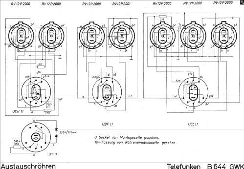
Die Adapter dürfen nur gemeinsam betrieben werden, da der Heizstrom von 0,075mA der Wehrmachtsröhren nur so realisiert wird. Der Austausch eines Adapters mit der jeweiligen U11-Röhre würde die Spannungsbilanz sofort stören.
- UCH11 = RV12P2000, RV12P2001 und 220 Ω-Widerstand im Heizkreis
- UBF11 = RV12P2000, RV12P2001
- UCL11 = 3 x RV12P2000
- UY11 = 2 x Selensäulen parallel und 900 Ω-Widerstand im Heizkreis
- Source of data
- Die Radio-Reparatur (329) / Radiokatalog Band 1, Ernst Erb
- Mentioned in
- Funkschau (4604)
- Other Models
-
Here you find 3546 models, 3126 with images and 2095 with schematics for wireless sets etc. In French: TSF for Télégraphie sans fil.
All listed radios etc. from Telefunken Deutschland (TFK), (Gesellschaft für drahtlose Telegraphie Telefunken mbH
Forum contributions about this model: Telefunken: B644GWK
Threads: 1 | Posts: 1
Hallo Zusammen!
Anbei die Vorstellung des Telefunken B644GWK in der Funkschau 1946.
Schöne Grüße und viel Spass damit
Dirk Becker
P.S.: Beim Telefunken B644GWK (U) handelt es sich um das gleiche Gerät nur ohne Austauschröhren.
Attachments
- Telefunken B644GWK (72 KB)
Dirk Becker, 16.Feb.07