2AS15 - How it works.
2AS15 - How it works.

Hello Radiophiles and tube enthusiasts,
The 2AS15 is an unusual thermionic diode. Unlike nearly every other diode, the 2AS15 was designed to run under temperature-limited emission. Nearly all tubes work under space-charge-limited emission.
Under space charge limited emission, the plate current of a diode goes up with the 3/2 exponent of the plate voltage. This characteristic is modeled by the familiar Child-Langmuir law.
Under Temperature limited emission, there is sufficient voltage at the plate that all electrons that boil off the cathode surface are collected at the plate, and further increases in plate voltage add very little plate current.
Space charge limited emission is separated by temperature limited emission by a critical voltage.
The only other class of diodes that is meant for operation under temperature limited emission are noise diodes - diodes that are used in noise generators.
Rare earth cathode coatings are usually not suited for temperature limited emission because they rely on the space charge to protect them against ion bombardment from vestigial gases. This is one reason why it is better to heat a tube first, and then apply the plate voltage.
Temperature limited diodes have cathodes that are not coated with the usual fragile rare earth coatings. They have bare metal cathodes.
The 2AS15 has such a bare metal cathode. Probably tungsten. The poor emission of a bare metal cathode makes it necessary to run the cathode at higher temperatures.
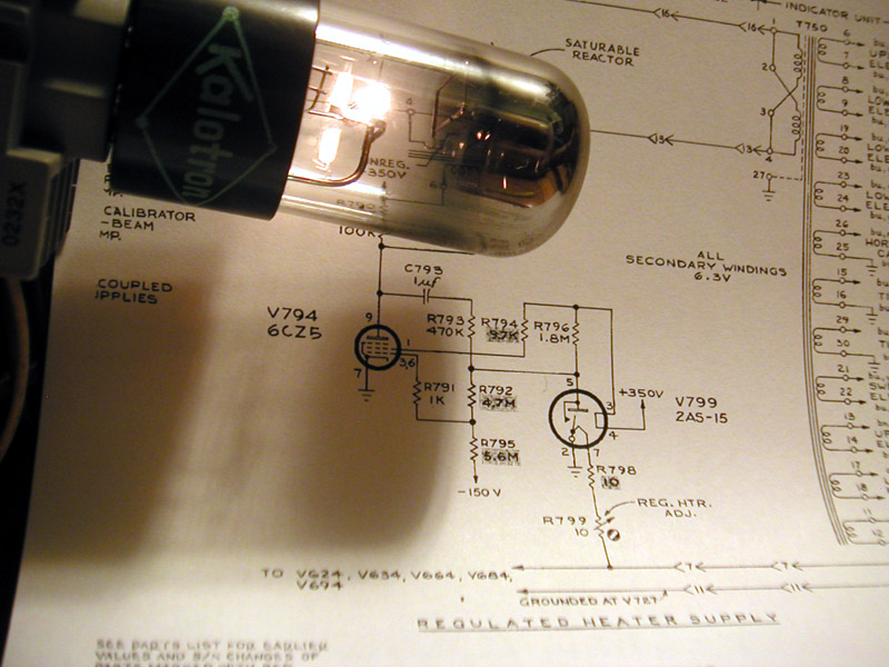 This photo shows the 2AS15 under normal glow. The glow is comparable to that of a common flash-light.
The temperature-limited emission of the 2AS15 is very sensitive to the applied filament voltage, but very independent from plate voltage above 20V.
This characteristic is employed to sense heater voltage in heater voltage regulators. One such example is the heater power supply in the Tektronix 555 oscilloscope. The DC accuracy of this oscilloscope is in a significant part helped by it's regulated heater supply.
Heater regulators need some fail safe protection to avoid applying too much voltage to the heaters under regulation, in case the 2AS15 burns out.
One such protection is the interlock jumper between pins 3 and 4 that is meant to shut down the heater supply, or force it to the low end of the regulation range. This type of interlock is very common in regulating gas diodes, such as the 0A2 or 0A3.
Another fail-safe protection is in the form of a switch that closes when the filament physically opens up. The filament is tensioned by a spring wire. when the filament opens up, the spring wire makes contact to a rod that is connected to the plate. This is meant to simulate extremely high emission, thus forcing the heater regulator to the low end of the range, until the open 2AS15 is replaced.
The following schematic shows the 2AS15 sensing the voltage on one of the heater transformer 6.3V secondaries. Both fail-safe features just described are employed in the Tektronix 555 heater supply.
I could not find a data sheet for the 2AS15, but this application revealed it's operation.
The 2AS15 is the sensing element in a closed loop regulation system. It's plate current is sensed by the 6CZ5 beam power pentode, which sets the DC bias current of a saturable reactor. This reactor acts as a variable impedance in series with the heater transformer.
The heater winding that drives the 2AS15 heater also drives 5 other tubes. This helps to mimmic the loading effect on the other secondaries.
The 6CZ5 tube and saturable reactor comprise the high gain power amplifier, and can be understood as an Operational Amplifier. As such, the control grid operating voltage can be approximated with zero volts. This is akin to the zero volts present at the inverting input of an OPAMP.
From this we calculate a current flow through R795 5.6Meg to be 150V/5.6Meg=27uA.
This current also flows through R792 4.7Meg, thus bringing the plate of the 2AS15 to 126V.
The current through R796 1.8Meg at the 2AS15 plate is (350V-126V)/1.8Meg=124uA
This forces the 2AS15 plate current to 124uA-27uA=97uA.
The operating filament voltage at the cathode, after the two 10 Ohm resistors is the voltage that gives this plate current when the plate is 126V.
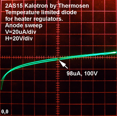 This curve trace of the Anode current shows an anode current around 100uA with 126V at the plate. The slope of the curve is 100V/10uA=10Meg
The filament voltage and current that produced this curve were 1.6V and 330mA.
The cold resistance of 2AS15 was 0.62 Ohms.
The hot resistance was 1.6V/330mA=4.85_Ohms
This 7.8 fold resistance increase over room temperature at 300oK suggest a filament temperature around 300oK*7.8=2350oK. This is much higher than for a common red glowing tube, which is well under 2000oK.
The variable 10 Ohm resistor R799 is used to fine tune the 6.3V operating heater voltage of the oscilloscope.
As a final sanity check, we calculate that the external resistor driving the filamentary cathode would be (6.3V-1.6V)/330mA=14.2 Ohms. This is at the center of the 10-20 Ohm adjustment range of R798 in series with R799, so our calculations should be OK.
A more precise calculation could have been done by taking into account the negative bias voltage that the 6CZ5 needs to run at the center of it's linear range. This voltage is around -14V at the control grid, with the screen biased near 250V.
C793 and R793 form a pole-zero pair to stabilize loop operation. Under open loop conditions, the pole runs near 1/(2*pi*1uF*1.5Meg)=0.1Hz, and the zero runs near 1/(2*pi*1uF*470k)=0.3Hz
Regards,
-Joe
To thank the Author because you find the post helpful or well done.
Data Sheet from Ludwell Sibley
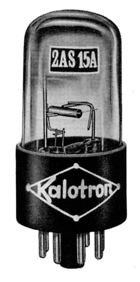 Ludwell Sibley has kindly sent me the data sheet for the 2AS15 Kalotron by Thermosen.
The filament tensioning spring wire is visible as the thinnest horizontal element in the photo.
The metal rod that it touches when the filament opens up is visible as the L shaped element welded to the plate support rod.
The curve family show below shows a 100uA separation between the 1.6V and 1.7V curves when the plate is 125V. This gives a transconductance from filament voltage to plate current of 1mS. (Yes, it is OK to think of transconductance from filament to plate because that is how the heater voltage signal is transferred to the plate current)
This transcoductance results in a voltage gain from filament to plate of 1mS*(1.8Meg//10Meg)=1500. The internal plate resistance at this operating point is 10Meg, as mentioned in the previous post.
The gain from 2AS15 filament to the control grid of the power pentode V794 6CZ5 is only 700 because of the attenuation of R792 and R795.
This very high gain of 700 in front of the power pentode means that any DC bias variations at it's grid affect the regulated 2AS15 filament voltage at the cathode pin7 by 1/700. A 1V bias variation at the control grid of the pentode forces the filament voltage at pin 7 to change with feedback around the loop, by only 1.4mV.
Lastly, the 6.3V present at pins 11 and 12 of the heater transformer, is attenuated by R798+R799=15R by 1.6V/6.3V=0.25. This attenuation gives a total gain from the heater transformer secondary to the power pentode control grid of 700*0.25=175.
So a 1V bias fluctuation at the control grid of the power pentode results in 1V/175=5.7mV variation in the 6.3V heater voltage at the heater transformer secondaries. Still pretty darn good!

Lud also sent me a list of similar tubes. I quote his list as follows:
------------------[snip]
Thermosen had a wide line of Kalotrons. Besides the 2AS15A, there were a:
2AC15
2SM15
1236C (Sylvania-originated)
5MD5
5DC5M
5DC5
8DC15
8DS15
------------------[snip]
Thank you Lud, for sharing a tiny bit of your prodigious tube knowledge.
Regards,
-Joe
To thank the Author because you find the post helpful or well done.