wkelectric: 3 Cathode Follower RF stages and 2-tank regeneration
wkelectric: 3 Cathode Follower RF stages and 2-tank regeneration

Fellow Radiophiles,
The Winther-Kenosha sets are unique for featuring cathode follower RF amplifiers. While many contemporary sets of the mid-1920's were likely to break into spurious oscillations, these sets never did because of the cathode follower architecture in the RF stages. The voltage gain for each RF stage is accomplished with a loosely coupled resonated voltage step-up transformer that is driven by the cathode of each stage or with a wide band untuned step-up iron core transformer. The Winther-Kenosha 71 Warwick is one of the better W-K sets with three cathode follower RF amplifiers and the grid leak detector has a transformer load at it's cathode to drive very well controlled regeneration over the second and third cathode follower RF stages. There is a total of 4 cathode followers in this set. See also the report on the Oriole 8 with a single cathode follower RF stage.
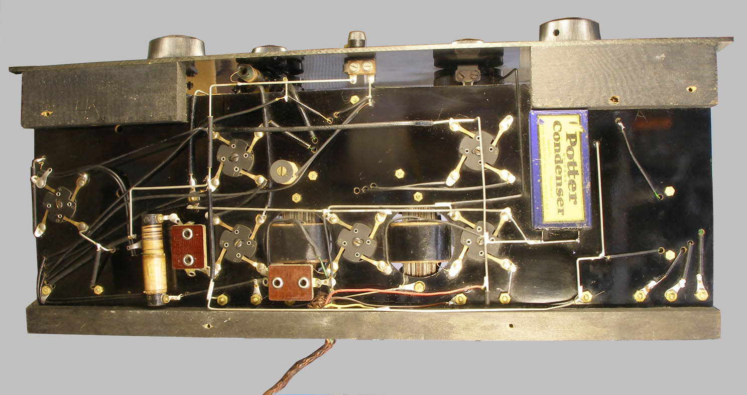
The following excellent photos of the chassis and the photos of the volume rheostat were provided by Robert Lozier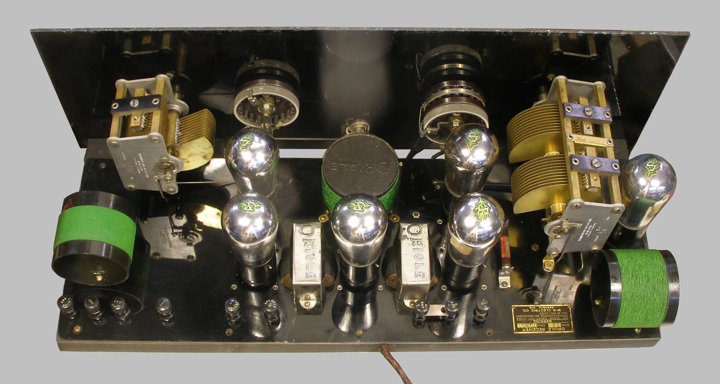
 The traced schematic shows measured values from my set.
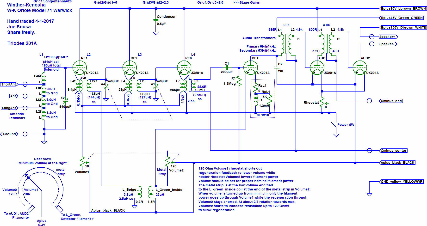
The measurements were taken with the volume control set to the 2/3 rotation just before it applies regeneration.
The first tank couples the antenna and ground inputs to the first cathode follower RF stage grid. This first tank is tuned independently with a variable capacitor. The second and third tanks in the two cathode follower RF stages are tuned with a ganged pair of variable capacitors. The predictable and stable input reactance of the cathode followers makes it possible for the tuned pair of tanks with a Q=125 to track very well over the entire AM band to better than 1%.
In conventional contemporary sets with grounded cathode triode RF stages, the effect of Milller capacitance from plate to grid depends on stage voltage gain, so that when filament power is adjusted, the stage tuning is altered slightly. Such an effect is greatly reduced with cathode followers because the feedback capacitance is from cathode to grid and in a much smaller amount as can be predicted by the ratio of gains from grid to plate on the order of 5 for grounded cathode or from grid to cathode on the order of 0.5. The cathode follower feeds back via parasitic capacitance on the order one tenth of the voltage of a grounded cathode stage. (The plate-grid Miller capacitance effect was very pronounced in the 10.7MHz pentode IF stages of non-neutralized FM tube radios of the 1950's and 1960's. IF alignment depended on signal strength as larger signals reduced stage gain with limiting or AGC.)
When the lowest tap of the antenna tank was used with a 30ft antenna, the dial for the first tank and the dial for the other two tanks tracked within one tick, or 1% of knob rotation over the entire band. This tap (1.2uH) is thus very lightly coupled into a high Q=100 tank (165uH) to avoid detuning and also avoid reducing the tank circuit Q. The highest tunable frequency was about 2MHz.
This lowest input coil tap was also useful to connect a large single turn wire loop antenna. The loop is made of AWG22 wire wound on the outside of the 6foot by 3foot book case where the radio sits and has about 8uH of inductance. There is no danger of feedback from the coils in the radio because this loop is in the same plane as the antenna coil and at right angles to the other two coils. The third cathode follower RF stage drives the grid leak detector with a wide-band step-up iron core transformer. This transformer is a small solenoid visible as a yellow tube on the lower left under the chassis. This antenna picked up less noise than a 30foot indoor wire antenna I have running near the ceiling. The improved noise immunity is attributable to the magnetic loop antenna being insensitive to the electric field that is usually more poluted with man-made interference. With this loop antenna, I pick up nearly all the same stations as with a modern radio.
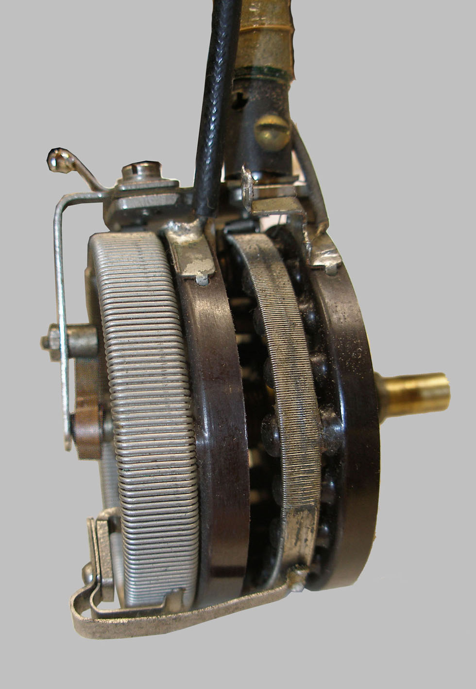
 There is a very clever "Volume" control made with a dual track rheostat. See the photos and the rear-view illustration in the schematic. One track with heavy NiCr wire is 10 Ohms and controls the filament current of the three RF cathode followers. The second track with fine NiCr wire is 120 Ohms and only occupies the top third of the volume control rotation, with a shorting strip for the first two thirds of the rotation. This 120 Ohm rheostat controls regeneration by shorting out the primary of a feedback transformer that is fed from the cathode of the grid leak detector. This feedback transformer is the solenoid air coil on top of the volume control in the photo. When the volume is turned up from minimum, only the 10 Ohm track decreases resistance to increase power to the filament. At about 2/3 clockwise front-view rotation, the 120 Ohm track starts to increase from zero and regeneration is gradually increased. The low impedance of the regeneration circuit helps make it insensitive to capacitive coupling from other circuits and the very low voltage levels that are inherent in a low impedance circuit prevent the regeneration circuit from radiating capacitively to other parts of the circuit.
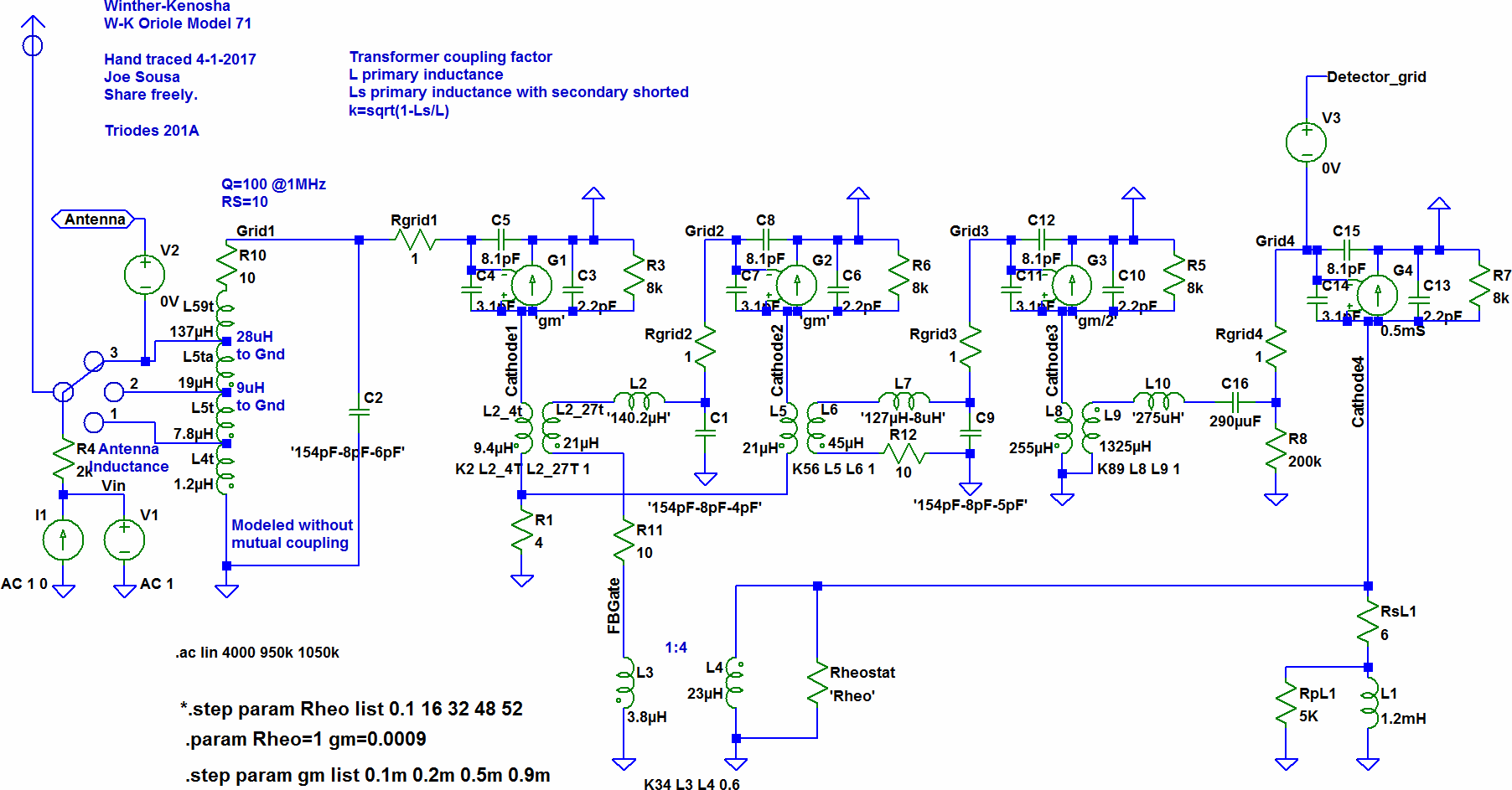
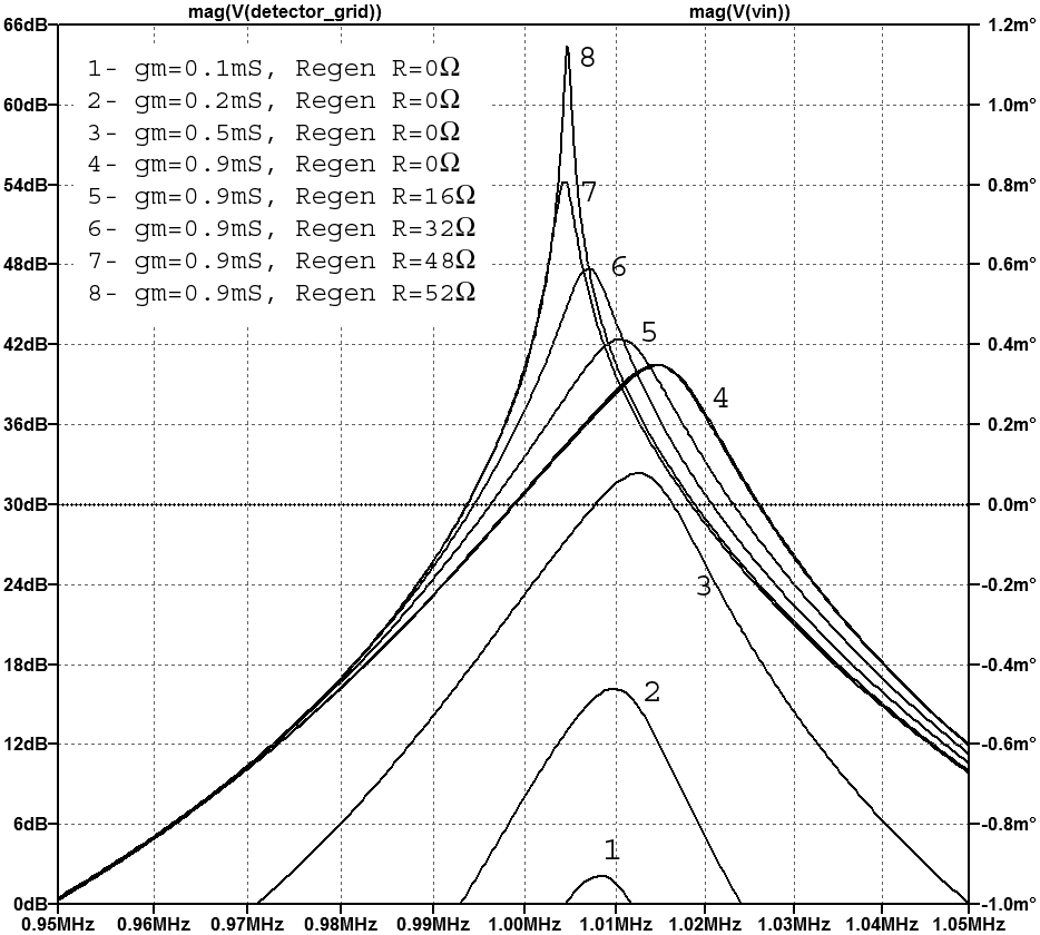 The measured values from my set were used in a simplified schematic to simulate in LTspice the small signal frequency response near 1MHz for various settings of the volume control. The plot shows various frequency sweeps at the detector output. Each sweep is done at a different volume control setting with it's two sections of rheostat. The variation of the 10Ω track of the rheostat that drives the tube filaments is represented with the resulting 4 levels of 201A tube transconductance of 0.1mS, 0.2mS, 0.5mS and 0.9mS. The 120Ω regeneration track of the rheostat was simulated with values from 0.1 Ohm to 52 Ohms. The regeneration control has enough range to oscillate over the entire range, but it's operation is not at all touchy, because it takes modest levels of regeneration to get very good results without surprise oscillations and whistles. Perhaps the best regeneration control I have ever worked with.
Also note that the regeneration operates over the two tanks of the second and third cathode follower RF stages, thus making the net bandwidth narrower than regeneration with just one tank as we will see in the following simulation.
The screenshot shows an LTspice simulation comparing regeneration over one tank vs two tanks. The curves represent transimpedance (output volts/input current) expressed in dBΩ.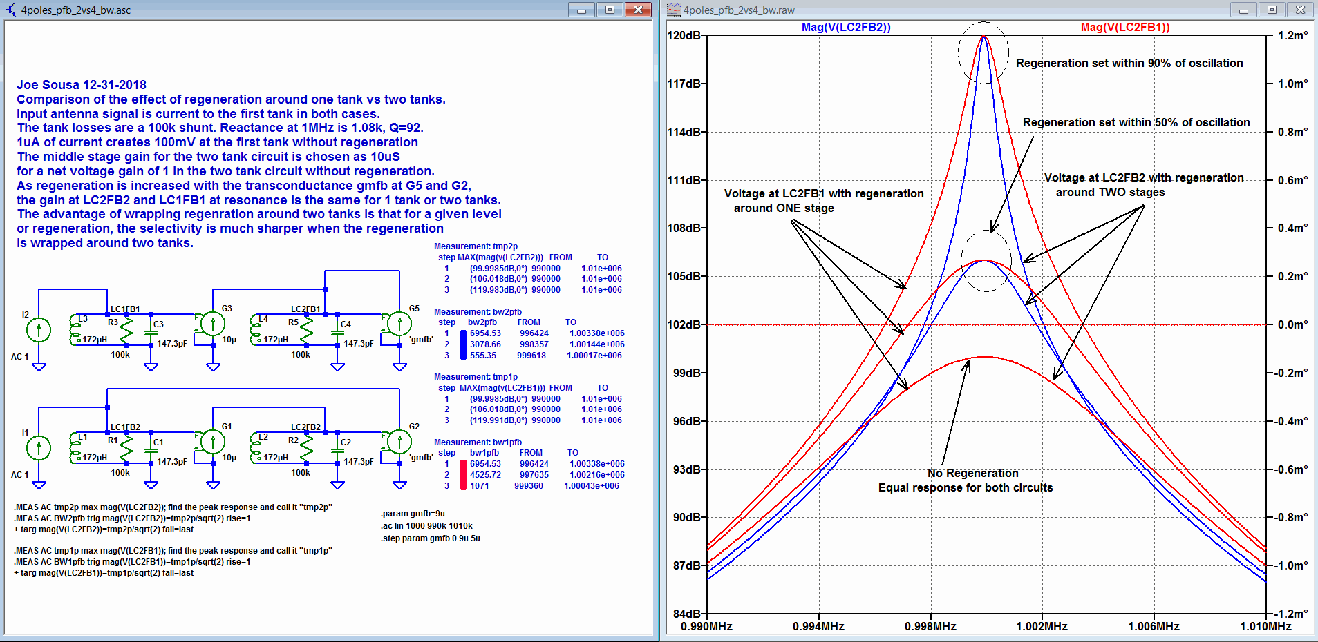
Adding a second tank inside the positive feedback regeneration loop improves selectivity without affecting the net regenerated gain at resonance. Shunt tank losses are 100kΩ and combine with the nominal 10uS transconductance for a forward net gain of one without regeneration at resonance. The simulation plot compares regeneration around one tank in the red trace family vs two tanks in the blue trace family. The gm of the PFB path is set to 0uS, 5uS and 9uS. These give 0%, 50% and 90% regeneration. 10uS would give 100% regeneration with a net loop gain of exactly one at resonance and would start oscillation instability. The blue and red curve families touch at the 1MHz resonance frequency and show that the net gain at resonance with regeneration is the same with one or two tanks. The difference between regeneration over 1 vs 2 tanks lies in the much narrower bandwidth with 2 tanks. This means that greatly improved selectivity is achieved with regeneration over two tanks, without having to get much closer to instability and oscillation to get the same selectivity with regeneration over just one tank. With 90% regeneration over two tanks, the highest blue curve shows 555Hz bandwidth, while regeneration over one tank in the highest red curve shows 1071Hz Bandwidth.
Thank you Ed Lyon for reporting on my findings for this radio In Radio Age, the monthly newsletter of the Mit-Atlantic Radio Club and thank you Robert Lozier for sharing the wonderful photos and new info on Winther-Kenosha and your careful listening experience with your W-K Oriole 71 Warwick. Thank you both for your encouragement.
Regards,
-Joe
To thank the Author because you find the post helpful or well done.