wkelectric: 5 Cathode Follower RF stages with 5-tank regeneration
wkelectric: 5 Cathode Follower RF stages with 5-tank regeneration

5 Cathode Follower RF stages with 5-tank regeneration
Fellow Radiophiles,
 Robert Lozier first found this set in original condition and performed a masterful restoration. Robert reported his restoration efforts, measurements and evaluation of the set in another post. The hand traced schematic diagram and some of the photos in this post were done by Robert.
This set is now in my collection. I am equally happy to have this set in my collection, as I am to have a masterful Lozier restoration! The photo shows the small 1.5" wide metal label that Robert affixed discretely on the lower right corner inside the lid.
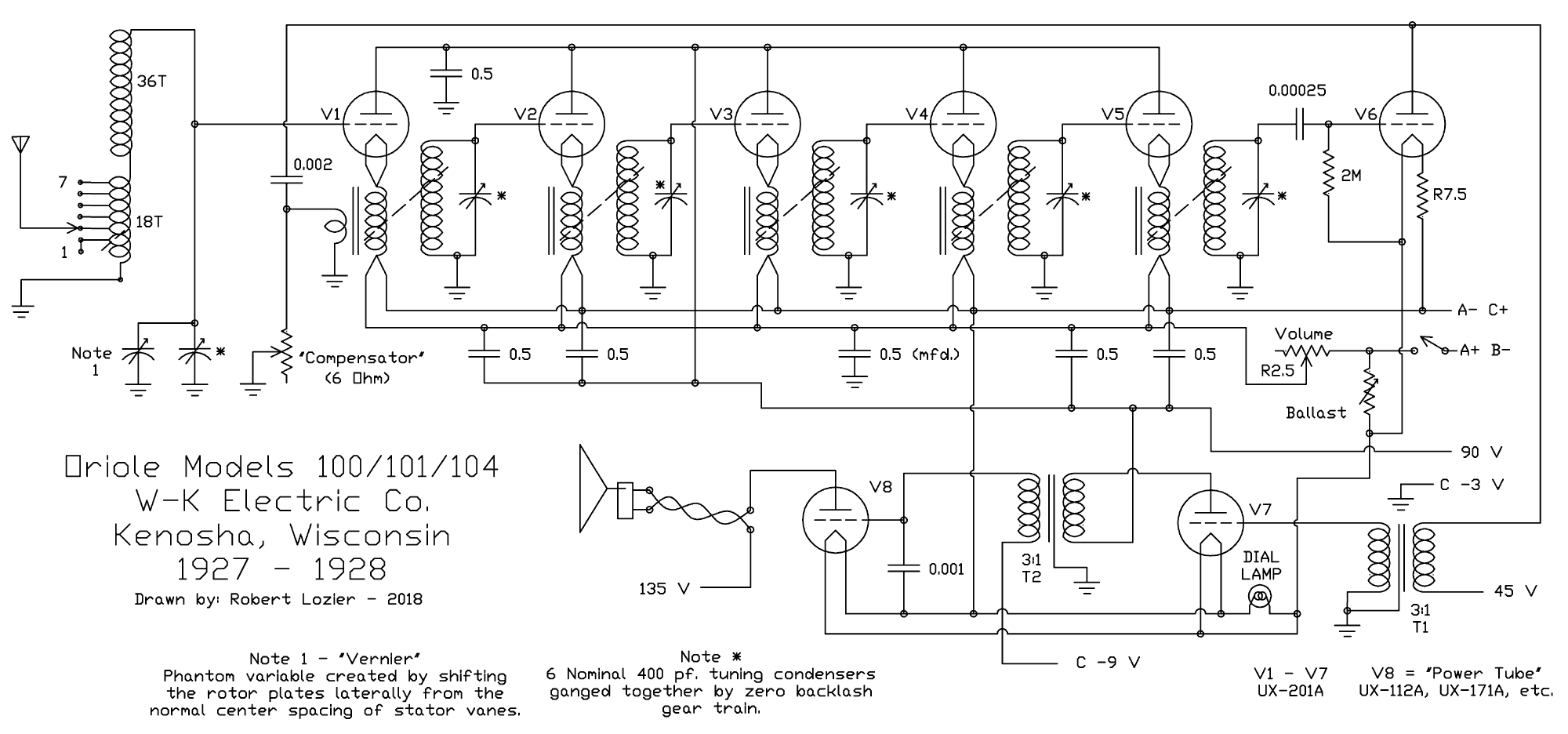
I will share with you my findings and measurements of the Oriole Model 100. The Oriole model 100 with five Trinum cathode-follower RF stages marks the top-of-the line for Winther-Kenosha (W-K). This model employs 6 equally tuned RF step-up tanks with 5 cathode follower stages coupling each step-up tank to the next, and eventually to the grid leak detector. W-K called their special cathode follower RF stage, the Trinum circuit. Their cathode-follower RF amplifier circuit received a patent on January 29th, 1929, although these sets were in production only from 1924 to 1927.
The following hand traced schematic shows all the plates of the cathode follower stages tied to the 90V B battery supply. The signal current is amplified from grid to cathode with power gain and the step-up tuned transformers provided the voltage gain to drive the grid of the next stage.
As reported earlier [1, 2, 3] for other W-K sets, the triode cathode-follower RF amplifier with step-up RF transformer offered oscillation-proof voltage gain up to 5x per stage, where conventional common cathode (a. k. a. grounded cathode) were very prone to oscillation at this level or even lower levels of voltage gain. These conventional grounded cathode amplifiers may have used neutralization to cancel the Miller plate-grid capacitance feedback, that would cause oscillations or may have used degenerative schemes to keep the unpredictable stage gain under control bellow the oscillation point. A comparison of plate loading vs cathode loading of tank circuits is available in this post about cathode reaction. Jochen Bauer gives a rigorous mathematical analysis of the effect of plate-grid feedback Miller capacitance in conventional grounded cathode stages, which can also be used purposely to increase regeneration and consequently gain.
The idea for a cathode follower design was also considered in England by Johnston, but the schematic diagrams that survive show that these designs were not capable of voltage gain due to the lack of step-up RF transformers from the cathode of one stage to the grid of the next stage. Only external overall regeneration would increase the set voltage gain, but at the risk of inducing oscillations. These designs offered one way to use a sequence of RF tank circuits to increase selectivity with negligible interaction between the tanks. This lack of voltage gain for each cathode-follower stage in these designs highlights the importance of the step-up transformer with the bifilar primary in W-K's invention.
RF Transformers in continuous development during the life of the W-K product line.
W-K had a relatively short production run of just a few years from 1924 to 1927. In the course of their production, they made several variants of their Trinum cathode-follower RF amplifier and employed different numbers of these stages in various sets. For example, the model 8 used just one RF stage, the model 7B used 3 RF stages and finally the model 100 presented here used 5 RF stages. All these RF stages use the Trinum Cathode-follower circuit for current gain and power gain with various configurations of step-up loosely coupled tuned RF transformer for a net stage voltage gain between 2x and 5x. The transformer variants had different secondary coil types, including simple solenoids and basket weave, but all used a bifilar primary solenoid winding with a few turns.
Bifilar means two wires in parallel to make a tightly coupled pair of windings. At RF frequencies, these wires are shorted at one end by the 20Ω filament and at the other end by the battery, thus presenting an equivalent single primary winding as the RF load. Each of the two bifilar windings passes 5V from the battery to the filamentary cathode terminals to make the filament glow and emit electrons for the amplification process. This unique filament power arrangement made it possible to share the filament battery for any number of RF stages. At DC, each of the bifilar windings passes DC power to the filament with negligible resistance.
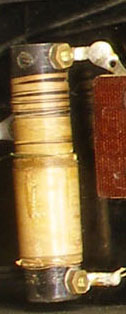
The model 100 has the further transformer variant in that the coil arrangement is in binocular style with solenoids placed adjacent to each other. The low Q=5 untuned primary has a smaller diameter and uses a laminated iron core. The tuned secondary has Q~85. The impedance seen by the cathode at the primary is always affected by resonance at the secondary. In The model 100 it is about 2kΩ at resonance and is higher than the cathode impedance 1/gm=1.25kΩ.
Four variants of the step-up RF transformer.
The first transformer in the following table is from the Model 8 with a single RF cathode follower stage and has the bifilar primary on the outside over a solenoid form with the tuned basket weave secondary inside it.
The three cathode follower RF stages in the model 71 use two tuned standard solenoid transformers with the bifilar primary inside and one untuned wideband high inductance laminated iron core transformer, also with a bifilar primary, driven by the third cathode follower stage.
The model 100 uses five identical cathode follower stages with step-up transformers arranged as binocular solenoid pairs. The narrower coil has the bifilar primary wound around a laminated iron core. All five secondaries in the binocular coils are gang-tuned simultaneously with a zero back-lash gear train.
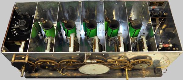
These coil sets in the model 100 have the smallest footprint in the W-K line. Each of the 5 stages, including the coil, sits inside completely shielded identical aluminum compartments. The stable high impedance of the cathode follower stage and the quality of the construction of the coils and tuning capacitors, and very short grid connections keeps all 5 stages in very good alignment, despite the absence of any form of obvious alignment adjustment. I verified the alignment of each stage at the bottom, middle and top of the dial by inserting a ferrite stick followed by a shorted loop into each coil to see if the alignment could be improved. (This is an old technique to check alignment. The ferrite stick increases inductance and the shorted loop decreases it. It works at any frequency because the inductance has the same nominal value at any frequency). To my delight, the alignment was excellent up to 1200kHz and both the ferrite stick and the shorted loop always detuned each tank! Above 1200kHz, a small trimmer capacitor in parallel with each stage capacitor could have improved the alignment on two of the stages.
| Oriole Model 8 | Oriole Model 71, The Warwick | Oriole Trinum Model 100 |
|---|---|---|
| 1 stage gain 3x | 3 stage gains 5x, 2.3x, 2x | 5 equal stage gains, 2.4x |
| Sec/Pri = 17x | Sec/Pri = 13x, 37x, 2.3x | Sec/Pri = 5x |
| uH/uH = 230/3.7 | uH/uH = 165/9, 172/21, 1600/255 | uH/uH = 224uH/175u |
| Basket weave secondary | 2x Tuned solenoid, 1x iron core | 5 pairs of Binocular coils |
 |
 |
The binocular solenoid pairs in the last figure sit in individual compartments of the aluminum model 100 chassis. An aluminum lid covers the chassis except for the antenna matching switch on the left.
It is interesting to note from the wide range of step-up transformer designs, that the Trinum circuit underwent continuous development in the 1924-1927 period when these sets were designed and made. Even sets with similar tube count and layout used different transformers: Models 71 and 7D used solenoid transformers, while the models 7, 7B and 200 used basket weave. The stage gains varied from 2x to 5x for the various designs, but even more interesting is that this was accomplished with transformers with step-up voltage ratios that varied from 2.3x to 37x. This points to very different design goals for each of these transformers.
For example, the 37x step-up ratio transformer for the second stage of the model 71 has the lowest impedance primary, which means it is the most loosely coupled of the designs, and therefor the most selective - loaded Q is nearly the same as the unloaded Q. The attenuation from the grid to the cathode at this stage is 1/16x for a combined stage gain of only 2.3x. Note that the step-up ratio of the tuned transformers is much higher at resonance and not directly related to the turns ratio. By contrast, The third stage of the model 71 uses an untuned laminated iron transformer where the step-up ratio is set by the turns ratio and is independent of frequency. It's input impedance is much higher than the 1.2kΩ source impedance of the follower cathode, so that the attenuation at the cathode from transformer loading is only 0.9x. But keep in mind that the mu=8 for the 01A triode also limits the unloaded cathode follower gain to 0.88 because of the internal tube resistance loading from cathode to plate, which is mu/gm=8/800uS=10kΩ.
 The plot shows the measured Q of the tuned secondary using the BW/f0 measurement method in the red trace and Robert Lozier's measurement with his Heathkit QM-1 meter. My Bandwidth measurements were more likely to have random errors as I estimated the -3dB bandwith points on the oscilloscope frequency sweep.
The five identical Trinum cathode follower stages in the Model 100 have an impedance matched primary to the 1.2kΩ cathode impedance. This gives a 0.5x attenuation from grid to cathode, which combines with a step-up transformer ratio of 5x at resonance for a combined stage gain of 2.4X. This transformer is unique in the Oriole line with similar primary (175uH) and secondary (224uH) inductances. The untuned primary has much lower Q~5 than the tuned secondary Q~85, but the primary is driven by the 1.2kΩ cathode impedance, which lowers the loaded primary Q~5 to Q~2.5.The coupling is still pretty loose with a 0.1 coupling factor, so that the lossy primary does not reduce the Q of the secondary.
The variable ganged tuning capacitors
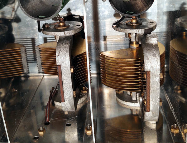 All five transformers in the model 100 are tuned with 400pF nominal variable capacitors. The capacitors are synchronized with a gear train that has a spring-loaded pulley between the 2nd and 6th tuning capacitors to eliminate mechanical backlash. The dial is mounted on the fourth variable capacitor shaft and is illuminated with a dial light, even though this is a battery set. The capacitor plates alternate rotational orientation on every other capacitor, because the gears on their shaft also rotate in opposite direction on every other shaft. As you turn the dial, you see the capacitors rotating out from the bottom alternating with caps that rotate out from the top.
The very good alignment from 550kHz up to 1200kHz justifies the top notch zero-backlash gear arrangement, but one can wonder, if the product line continued, the gears might have been replaced with a single common shaft running through all 6 tuning capacitors. The gears are all fixed to each capacitor shaft with a set screw in the wheel bushing. If there is a misalignment here, the top of the band will first fall out of alignment due to the much higher percent capacitance variation for any degree of rotational misalignment when the plates are nearly fully rotated out. This also means that slight tweaks to the rotation of the caps, perhaps of one degree or less, which is about half a tick in the 0-100 dial, could have been used at the factory to get the entire band to track very well. Half a tick has little effect on the tuning on the low end of the band.
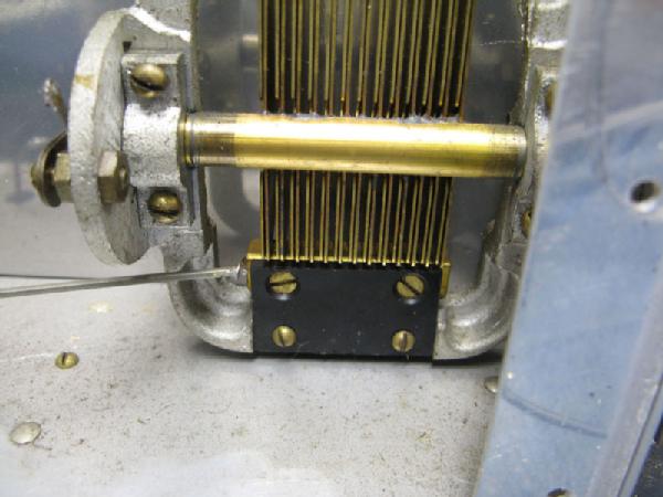
The special Vernier capacitance adjustment
 One of the problems with external antennas of unknown length is that they will detune the first resonant tank unpredictably. A well impedance matched coupling will give the most sensitivity, but this tends to detune the antenna tank. The seven taps on the input tank assure the best possible match to the antenna for peak sensitivity. One widely used solution to the antenna detuning effect was to have separate tuning for the antenna tank. Later radios with their much more sensitive superhet circuits used a very loosely coupled antenna hookup that had a negligible effect in the input tank resonant frequency.
But this set devised a very clever adjustment scheme that can be set to work with one setting for the entire dial with very little or no further vernier adjustment. The first tuning capacitor differs slightly from the other capacitors in that it's shaft can be pulled in and out with the "Vernier" control on the front panel. In the photo, the shaft moves left-right. This adjustment raises or increases the capacitance by the same percentage for any position of the variable capacitor as opposed to adding a fixed level of capacitance, as standard bandspread fine-tuning capacitors do. Changing the size of the entire variable capacitor is electrically equivalent to changing the inductance of the tank because changing the inductance at the tank also affects all frequencies equally. Once the vernier and input antenna tap are set for a particular wire antenna, or even for a loop connection to the front end tank, there is little need to touch the vernier as you tune stations along the dial. This realizes the goal of single knob tuning pretty closely.
Sets that offer an explicit Loop antenna connection usually swap out the first tank coil for the loop. In this set, my external loop antenna with 89uH inductance, worked with the antenna selector on the second highest tap #6. This tap #6 is at roughly 1/4 of the voltage at the top of the antenna tank. The vernier then gets the loop aligned with the rest of the set over the entire dial.
I have also achieved similar results with a 20 foot wire antenna, where selecting the correct antenna tank tap with an initial adjustment of the "Vernier" control produced nearly perfect alignment throughout the band. The user manual that came with the Oriole 100 suggested what tap to use, given the antenna lenght.
A further characteristic of the "Vernier" control is that it works very similarly throughout the tuning band. This is in contrast with standard fine tuning bandspread capacitors that are very sensitive at the top of the band, but hardly do anything at the bottom of the band.
Wide band tuning up to 1.75MHz
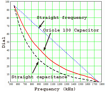 The cathode follower stage input grids have particularly low and predictable capacitance loading on the tank, so that the top tuning frequency reaches 1.75MHz. This capacitance is on the order of 10-12pF, which is dominated by 8pF from grid to plate of each triode cathode follower. This predictable low capacitance is essential for the quality of the frequency tracking between the 5 RF cathode follower stages. Many contemporary sets struggled to reach 1.5MHz. But there is significant crowding of frequencies at the top of the dial. The plot shows about 3x thighter frequency spacing at 1.5Mhz as compared to 700kHz in the red trace. The ideal straight line frequency shown in the blue trace uses capacitor plates that are specially shaped to linearize the inversion and square root in the resonant frequency formula: f0=1/(2*π*sqrt(L*C)). The off-center mounting of the semicircular capacitor plates on the shaft offers some improvement shown in the measured red trace, away from straight capacitance variation shown in the black trace with the shaft centered on the straight plate edge. Capacitor plates that are shaped to give evenly spaced frequency on the dial, shown in the blue trace, have longer narrower plates and the shaft is mounted near the corner of the straight edge of the plates, which makes them swing out much further. Robert Lozier points out in his article about this set that six straight frequency tracking capacitors with their long narrow plates would add 8 to 10 inches to the 26 inch cabinet width.
Modeling of the RF stages and Detector with simulation results
[click schematics and plots to enlarge]
The modeling of this set was done with the free simulator LTspice from Analog Devices (formerly from Linear Technology). Each tube is modeled with a transconductor with a nominal gm=800uS, which is the transconductance spec of the 01A tubes. The mu=8 for the 01A tubes was modeled with an output resistance of mu/gm=10kΩ. The individual interelectrode capacitances were entered from the data sheet as Cgk=3.1pF, Cpg=8.1pF, Cpk=2.2pF. This is only a small signal model. Previous experience modeling 1920's battery sets [1, 2, 3] has shown that the simulations for the overall set line up quite well with measured results, if the individual coil and tube models are first verified against measurement.
![]()
The RF Stage Step-up Transformers
The Step-up transformers were measured with the power off to establish primary and secondary inductances and their coupling factor. The coupling factor K=0.1 was extracted from two inductance measurements of one winding with the other winding first open and then shorted K=sqrt(1-Lshort/Lopen). The Q of each winding is modeled with resistor capacitor networks. The frequency response was measured at 3 frequencies near the top, middle and bottom of the band, at 1.5MHz, 950kHz, 600kHz, because the Q is not constant over the tuning range. The calculation of the resistances required iteration to match the simulated response to the measured response. First the series resistors were entered for the Q at 600kHz, then the series RC branches were added to lower the Q at 1.5MHz to match the high frequency response Q. When the RC branches were added, the series resistors were lowered slightly to keep the combined Q correct at 600kHz. Fortunately, this exercise was done only once for the 5 identical stages.
The Front end Antenna Tank
The tapped front end coil has 6 distinct taps but only one of these is used at a time.
In the physical coil, the 6 taps are all made on a solenoid coil that is wound over a basket weave coil. The solenoid is in series with the basket weave coil.
Modeling the front end tank can be done with a simple tapped inductor 6 times to account for each tap location in the winding.
The 6 series coil pair models all have the same total inductance, but different individual coil inductances, coupling factors and step-up ratios.
As was done with the step-up RF transformers, the losses that establish the Q over the frequency band were modeled first with a series resistor to account for the Q on the low end of the band where the resonant currents are highest. Then a shunt resistor was added to account for the Q at the top of the band. The additional series RC was needed to further depress the Q at high frequencies to match the measured results. The depressed Q at high frequencies is likely caused by skin effect losses.
The plots show the frequency response at 600kHz, 1MHz and 1.5MHz for the top of the antenna tank that drives the grid of the first cathode follower in the green traces and for the antenna tap #6 in the magenta traces. The curves are 10dB apart and show the expected ~3x voltage ratio from tap #6 to the top of the tank.
It should be possible to model the antenna tank as a series combination of 7 inductors with mutual coupling factors for each adjacent pair of coils. However, I don't know the technique to do this correctly. A couple of quick trials soon showed that physically unrealizable coupling factors were reach and had to be discarded. Perhaps someone can find a reference for this technique.
5 RF Cathode Follower Stages With Global Regeneration and Detector
The 6 coils modeled above are now combined below in 5 RF stages with the model for the 01A triode to create the small signal AC simulation schematic from the antenna tap to the detector stage. Note the addition of a regenerative feedback path from the G6 detector triode plate with the primary of the first audio transformer modeled as a 5H coil on the lower right, AC-coupled through C16=2nF to the regeneration control Rcompensator driving a small coil in the first step-up transformer on the lower left. C16 also serves as the audio filter of the grid-leak triode detector. C21=100pF models the self capacitance of the L1 audio transformer primary.
The regeneration control is labelled Compensator on the front panel. It is a 6 Ohm rheostat. The RF step-up transformer phase was verified as phase inverting and is denoted with phase dots on the primary and secondary coils for each RF stage. The regeneration is very effectively done over 5 tuned stages for greatly boosted selectivity without very much regeneration. See the comparison of standard single stage regeneration vs multi-stage regeneration near the end of the post on the Oriole model 71.
A further advantage of regeneration over so many stages is that the regeneration control has negligible detuning effect. This feature is pretty handy if you want to let the set break into oscillation and then retune slightly to kill the squeal and get oscillation lock with the incoming RF signal for very clean synchronous detection (I verified with a modern sensitive AM radio that no detectable squeal was radiated by this set). The fact that the detector at the end of the amplification chain is in the feedback path helps provide the necessary non-linearity for locking in the oscillator with the weakest possible antenna signals. Once the set is locked in, you can move the "Compensator" regeneration control in and out of oscillation without any squeals that would indicate detuning. As you increase regeneration, the audio bandwidth narrows while volume increases as expected, then after the set breaks into oscillation and locked synchronous detection, the volume drops again but with wider bandwidth and less distortion with self-oscillating synchronous detection.
The ability of the set to oscillate with the compensator control turned up is an indication of the good alignment of the coils. If the set is oscillating and you detune any of the coils with a ferrite stick or a shorted loop, the oscillation stops. The alignment of the set can thus be verified by ear with high regeneration just short of oscillation. Dip the ferrite stick and shorted loop alternately into the coils to listen for increased or lowered volume. The strong effect that alignment has on regeneration makes checking the alignment by ear nearly as effective as using an oscilloscope or AC RF voltmeter to monitor the output.
AC Simulation Results for 5 RF Cathode Follower Stages and Detector
 This plot shows the simulated set response from the lowest antenna tap T1_2 to the detector grid6 for 600kHz, 1MHz and 1.5MHz without any regeneration and with perfect alignment. Compare this plot with the plots above for each step-up RF transformer and for the antenna coil. The curves in this plot range about 200dB, while the curves in the plots above range about 50dB.
Stage gains
The plot shows the progress of a 1MHz signal from the lowest antenna tap in the black trace at -24dB to the detector grid6 in the top dark blue trace at 54dB. The Compensator regeneration control is set to zero. This is a comparison of voltages in dBV. Note that the single largest voltage gain is 27dB at the antenna tank from -24dB in the black trace to +3dB in the blue trace. The total RF stage gain is about 50dB, which is a bit higher than the measured gain of five 2.4x stages 2.4^5=80x or 38dB. Note the -6dB voltage drop from the first grid1 to the first cathode1. This shows fairly good impedance match from the cathode to the step-up transformer primary. Note also how the curves become progressively steeper with each gain stage, with the steepest curve at the detector grid6 in dark blue and the shallowest at the first cathode follower grid1 in medium blue. The antenna tap in the black curve is also much less selective than the top of the antenna tank at grid in the blue curve. This is a low Q connection to the external 2kΩ equivalent antenna source. I might have added a couple hundred pF to the source driving the tap to simulate a real antenna.
The following table shows gain measurements at 600kHz, 1MHz, 1.5MHz. The mid band measurement at 1MHz was done twice with the signal injected at the lowest tap T1_2 of the antenna tank and at the first cathode follower grid G1 at the top of the antenna tank. The Volume control that sets the filament voltage for the cathode was set to get 5.25V. The stage gains are reasonably close to the simulation results. Note that a small variation in stage gain has a cumulative effect on overall gain.
| Dial | Frequency | In=T1_2 | In=G1 | Out=G6 | Total Gain | Stage Gain |
| 85 | 600kHz | 100mV | 3V | 30x=30dB | 2.0x | |
| 30 | 1MHz | 14mV | 8V | 672x=55dB | ||
| 30 | 1MHz | 100mV | 7V | 70x=37dB | 2.3x | |
| 20 | 1.2MHz | 100mV | 9V | 90x=39dB | 2.5x | |
| 10 | 1.5MHz | 100mV | 9V | 90x=39dB | 2.5x |
The Compensator
The compensator regeneration control. The plot shows the set response at 1MHz for various values of the Compensator regeneration rheostat. The blue curve with the soft peak has negligible regeneration with 0.1Ω at the Compensator rheostat. The next curves have 0.8Ω, 1.2Ω, 1.6Ω. The magenta curve with 1.6Ω shows signs of oscillation with the very sharp peak.
Note that increasing regeneration with higher values of Rcompensator would produce again softer peaks in the simulation result, but with oscillation present. There is mild detuning from no regeneration in the blue curve to the next red curve, but very little detuning for the remaining curves. When you tune to kill the frequency beat squeal for locked oscillation, you are using the magenta curve, so that reducing regeneration from that point does not cause detuning squeals and the slight detuning well below oscillation is not noticeable.
The power supply system
| Supply | Voltage | Current |
| A+ | 6.3V | 2A |
| B+ RF, audio | 90V | 20mA |
| B+ detector | 45V | 1.5mA |
| B Audio Out | 135V | 10mA |
| C Audio In | -3V | 0 |
| C Audio Out | -9V | 0 |
Refer to the traced schematic above for the power supply system. Note the extensive bypassing with 0.5uF capacitors between the 90V plate supply of the cathode followers and both bifilar RF transformer primary AC ground connections. These connect directly to A- and through the 2.5Ω Volume rheostat to A+. The A+/- terminals are fed with a conventional 6.3V Lead acid accumulator. It is not too surprising that the extensive RF bypass is necessary, given how little resistance is needed in the regeneration rheostat, which is only 6Ω, to drop the feedback current from the detector plate. The promise of the cathode follower architecture is to be free from oscillation and the bypass caps help full that goal. The original capacitors are leaky, but work well otherwise and Rober Lozier wisely left them in with his restoration. Perhaps one reason that each RF stage has an inverting step-up RF transformer connection is to reduce the net RF plate current, by perhaps a factor of 2, as each RF stage cancels about half of the plate current of the previous stage.
The "Volume" control
The "Volume" control is the classic series filament rheostat with 2.5Ω and is also the ON/OFF control. The total filament current is 2A with the 8 tubes, and dial light. The volume control adjusts the filament voltage of the RF stages to 5V or less for reduced volume, so it should not be increased to the lowest resistance value that would apply 6.3V from the A battery to the 5V filaments, unless the external supply is 5V.
This kind of "Volume" control by reducing thermionic emission with reduced filament power and thus reduced transconductance (gm), was universal in battery sets of the 1920's. It saved a little bit of A battery power, and a significant amount of B+ power from 90V. The filament emission current drawn from the 90V B battery and the volume drop off steeply if the filament current is reduced to 80%. Another advantage of this method of volume control is that it could use the common low resistance rheostats of the 1920's and did not introduce distortion with strong local signals. Lowering the B+ supply voltage would introduce distortion with strong signals because of cutoff and would require high resistance potentiomenters that were not invented until the end of the 1920's [4]. High impedance attenuators that became universal as volume controls a decade later in superhet sets with AGC, had yet to be invented. In sets that had a tendency to oscillate, the filament power control was also one way to kill the oscillations.
The Detector
The detector tube has a further 7.5Ω filament ballast resistor to run the tube with reduced emission to sharpen it's detection knee. The grid leak resistor is tied to A+ to ensure a predictable grid current bias regardless of plate voltage or filament current. (Grounding the grid leak bias, as is done in some sets, makes the grid bias current a strong function of filament current and plate voltage because the bias current is established by the built-in potential that is generated by the space charge)
There are two C grid bias sources at -3V and -9V. The -3V source sets the grid bias for the cathode followers and audio preamp. Note that chassis ground and antenna ground are tied to the -3V bias source. Chassis ground and antenna ground are not the common point of the A, B and C batteries as is often the case for contemporary sets. The -9V C bias sets grid bias for the output audio power tube type 01A. A 71A power triode can also be used, but requires -27V of C bias.
The 2 Audio Stages
The 2 audio stages, the dial light and the detector tube get their filament current from the 6.3V A+ terminal through a common ballast resistor to get their filament voltage near 5V. All tube filaments are rated for 0.25A from 5V. The two audio transformers appear identical. The primary measures 620Ω and 5.1H, the secondary measures 4.8kΩ and 44H. The step-up voltage ratio is 3X. The output of the radio is the plate of the type 71A power tube. A load impedance of 3.5KΩ is recommended by the 71A tube data sheet to deliver 370mW of undistorted audio power with a 135V supply and a -27V bias. The -9V bias level is recommended for use with the lower power tube type 01A.
The second audio transformer has an open winding. Rober Lozier left the transformer in the set unconnected and put in a small NPN transistor amplifier [5, 6, 7] replacement. This amplifier has a voltage gain of 5.7, which is near typical audio step-up transformer turns ratios in the 1920s, but more than the 3x of the audio transformer in the set. The NPN amplifier works fine and is capable of 70Vp-p swings with a 90V supply One unfortunate aspect of the design is that the ground current of the NPN amplifier passes through the -9V C bias connection. Usually there is zero current drawn by the grid from the C- battery, but the NPN amplifier draws about 1mA through C-=-9V with the power on and about 20uA with the power off. A separate connection for the 470k grid bias resistor in the NPN amplifier would have eliminated any draw from the C- battery. This is not a fatal flaw; the little NPN amp works fine otherwise. On closer observation of the PCB, it is clear that an extra pin is available for the 470k bias resistor. The pin can be separated from the ground connection with a cuttable PCB trace at the lower right of the board. With this option, the current from the C-9V bias source drops to zero.
User manual
W-K put out a very thorough user's manual that includes clear set-up instructions as well as debug instructions. The manual can be downloaded on the main model page for this set.
Thank you Robert Lozier for the masterful restoration of this set. Analyzing and learning from this set gave me the opportunity to appreciate the overall production of radios from Winther-Kenosha with their excellent Trinum circuit with cathode follower RF amplifiers.
Regards,
-Joe
Attachments:- Tune sweep (22 KB)
- Stepped regen (20 KB)
- AC sweep (31 KB)
- tuning dial (12 KB)
- Stepped regen schematic (53 KB)
To thank the Author because you find the post helpful or well done.