For Beginners: Reading Schematics (Circuit diagrams) Part 1
For Beginners: Reading Schematics (Circuit diagrams) Part 1
Reading Schematics (Circuit Diagrams) Part 1.
Schematics (USA) or Circuit Diagrams (UK & Ireland) are 2 dimensional drawings of a physical Electronic circuit that can be more than one part and on more than one layer. In this sense it’s a bit like the idea of Architectural plans for a Building, Engineering Drawing of mechanical part or assembly or even the map of a transportation system like the London Underground.
The Electronic schematic or Circuit Diagram is in some ways simpler. Each symbol represents an electronic component in a Logical sense (not its appearance) like the circle for a Station on the London Underground.
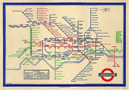
Innovation: London Underground map 1933
Note that the Underground map only shows the interconnections and relationships of the stations. It’s not remotely to scale and only vaguely geographic. The lines are the connections between stations, these are actually railway tracks, but the length isn’t really important. Before 1933 the Underground Map was drawn like a real map, not a schematic as above!
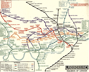
London Underground map 1932
In the earliest days of Electronics in the 19th Century and sometimes even up to the 1960s circuits were often drawn as simplified diagrams of the Illustration type, in the sense of the 1932 map.
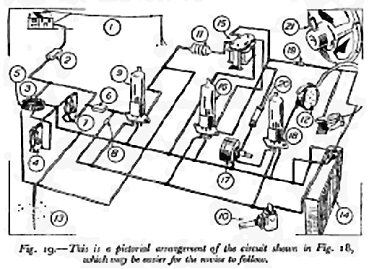
fig1. F.J. Camm’s diagram for Beginners in 1956!
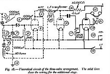
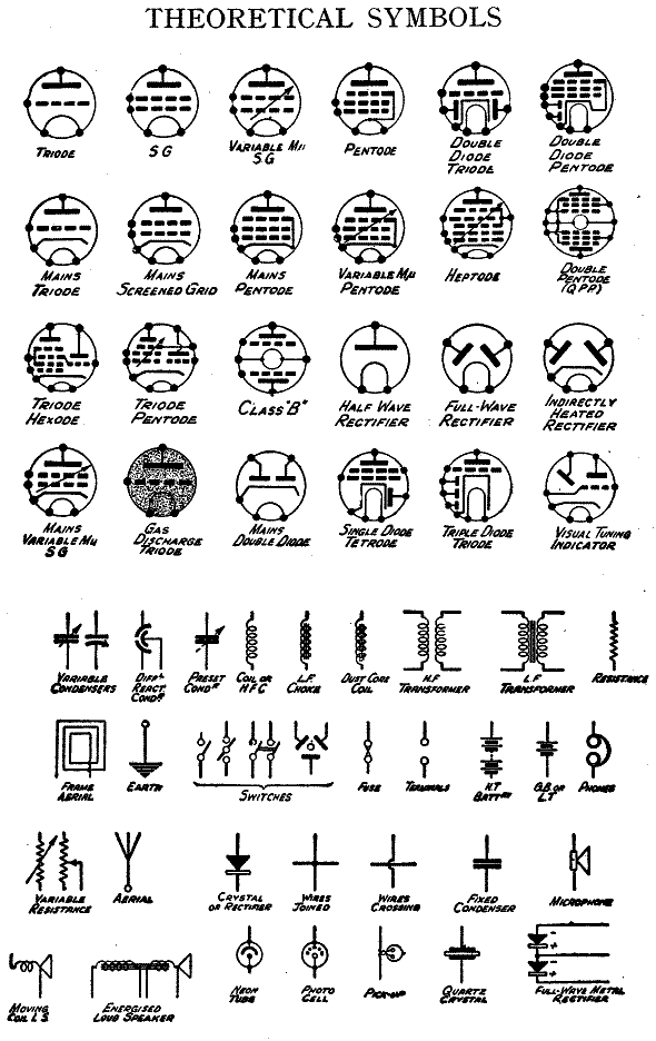
fig 2. The same radio shown as “Theoretical Circuit”

fig 3. Another style by F. J. Camm 1956
Here is a modern European style circuit:
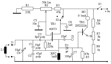
fig. 4 European Style
The lines are representing wires. The schematic doesn’t tell you if they are really wires, stranded, solid, tag strip connections (D1, C7, R5 and TR2 might not be connected to wires but all soldered to a common “tag” insulated from the chassis). Or the connections could be printed circuit tracks. It’s not normally important. The “thick” line represents Zero Volts, or “Earth” or 0V or “Ground” or “Common” or Chassis. It’s just indicating that these parts are all connected to each other. Sometimes the thick line might mean the connection (connecting wire) is via the low resistance of the metal chassis or a dedicated layer on a PCB (Printed Circuit Board).
You’ll notice on F. J. Camm’s Circuit Diagram some little hoops. This means the wires cross without electrical connection. He shows connections to a wire by a dot, like a blob of solder!
Anyone experienced will immediately actually spot what fig 4. actually does (if you do, you don’t really need this article!) and possibly what the application is, even if they have never seen it before, because not only does it use standard symbols, but it follows common layout conventions too such as input on left, power at top, 0V or ground/common at the bottom., the orientation of TR2 2N2222A and the output on the right. Sometimes these conventions are validly ignored in more complex circuits.
Step by Step. Symbols from 1921 to 2012
Wires (connections between parts)

fig 6. Wire connections
- A connection between 2 or more parts.
- A junction of two wires connecting.
- Four wires connecting. Only 3b and 3C are used today as 3 and 3a are ambiguous. The “dot” on 3a can vanish on copies.
- Two wires crossing. 4a is rare. 4b is less common now as only 3b & 3c are used generally.
It’s possible to see 3 & 4 on the same 1940s diagram. Only context (understanding the circuit) reveals if it’s four wires connecting or two wires crossing and not connected. When drawing by hand only use 3b or 3c for connections and only 4b for unconnected wires crossing. On CAD / CAE it’s acceptable to use 4, only use 3b or 3c for four wires connecting!
Resistors
Resistors and coils can be confused!
The current is always I = V/R. If R is kilo Ohms, Current is mA (milli-amps). If R is Mega Ohms the current is in uA (micro-amps). If you have 10,000V and 1K the current is 10,000mA = 10 Amps
Power rating needed is always I2 x R We often use * for multiply so Power in Watts is P = I2*R. The power is also P = V2/R Usually the power is only marked if larger than normal. By default ¼ Watt resistors are common.
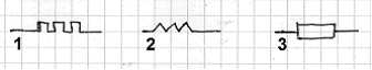
fig 7. Resistor symbols
- Vintage style, early 1900s
- US and UK style
- European mainland style (Also Philips in UK)
Resistors were initially only low value wire coils. Grid leak resistors then added as carbon in glass fuse like holders. Most resistors (not surface mount) are cylindrical with axial wires, looking like symbol “3” from the side.
Wires are actually just very low value resistors, and resistors are like wires that are a poor connection (a high resistance to current flow). Even if power limit isn’t exceeded, the very high value resistors may not be able to dissipate full power due to voltage rating. Similarly low value resistors have a maximum pulse voltage (can be 200V on smaller parts) even if average power isn’t exceeded.
Coils A.K.A. Inductors
Coils are simply longer wires. If they are coiled up the inductance increases, often proportional to N2 where N is the number of turns in the coil. An old name for the Inductor is “Choke” when it is to block mains hum or RF rather than part of a tuned cicuit.

fig 8. Coil or Inductor or Choke symbols
- Vintage coil symbol
- US & UK traditional symbol
- Mainland European symbol
A plain inductor symbol often means the coil has air core. Higher value inductors may use iron dust or ferrite core to increase inductance. Such cores are not conductive, hence rows of dashes (2a). There are various patterns in the box or the dashed lines like US/UK coil on the European symbol. At lower frequencies such as mains or audio the core may be sheets of steel to increase the inductance, hence the parallel line symbols (2b). If the core was solid it would act like a huge number of short circuited turns. It’s not uncommon to see a schematic use US/UK coil symbols but European resistor symbols.
A perfect Inductor has no effect on a steady DC current no matter what inductance it has. As the current changes faster the Inductor has more effect in the circuit. See Basic Electronics.
Capacitors
These are essentially two wires that are insulated from each other. The simplest method is two plates with a thin insulation to isolate them of air, vacuum, oiled paper, waxed paper, aluminium oxide, mica (a natural transparent mineral), ceramic or plastic. This is reflected in the symbols

fig 9. Various capacitors
An old name for a capacitor is a Condenser. The + and - symbols for polarity are not often shown on the schematic. Sometimes any of the first four symbols are used with a + to indicate polarity. To get more capacitance in a small space the capacitor can be constructed of two foils offset slightly on a thin flexible insulator and wound to make a cylinder. One wire can be in the centre and the other clamped to the outside to make the two wires exit at same end (Radial), or the wires can be pressed against pressed down foil where it sticks past the insulator, giving axial connections at opposite ends. Even if the capacitor isn’t polarised, one side is thus an “outer” and can screen the part if that side is regarded as earthy. This can be indicated on the case. Paper, Mica, plastic, air, vacuum and ceramic insulators (dielectric material) are not inherently polarised so the capacitor can connect to AC or DC at any way round. Aluminium or Tantalum based capacitors and all “Electrolytic” capacitors have a special conductive liquid. One sheet or side of the capacitor has a very thin film of oxide formed by reaction with the liquid in vintage parts or on modern parts merely maintained by the liquid. If the DC voltage was reversed the film would dissolve and the part catastrophically fail (explosion and/or fire is possible). So correct polarity (+ & -) connection must be observed on replacement. Paper insulation may only last 15 years. Mica virtually forever unless physically damaged
Batteries Switches and Lamps
Lamps can also be called Bulbs or Indicators.
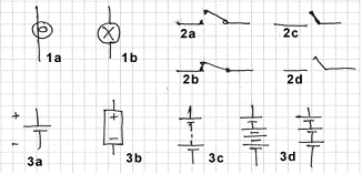
fig 10. Lamps, switches, cell and batteries
- Two common bulb/lamp symbols
- 2a is normally open (off: push to make) and 2b is normally closed (on: push to break). 2c and 2d are alternate styles
- A single cell (3a or 3b). No common cell is actually 1.5V, that’s a nominal value. A battery is a collection of cells (3b, 3c or 3d).
There are very many symbols for switches. In the next part we will “decode” some German Radio push button arrays.
To thank the Author because you find the post helpful or well done.
Some more Symbols

In 1941 Camm presents the following symbols in "Camm, F.J.: Practical Wireless Service Manual, 3rd ed. Georges Newnes Ltd., London, 1941"
In Germany, different symbols were used.
In the book "Handbuch der Funktechnik und ihrer Grenzgebiete, Bd. 9; Fortschritte der Funktechnik, Bd. 6, Franckh, Stuttgart, 1941" the following symbols are shown.
Please note: there is a change in norming the symbols by 1941.
Especially, the battery symbol was reversed (!), which should be kept in mind.

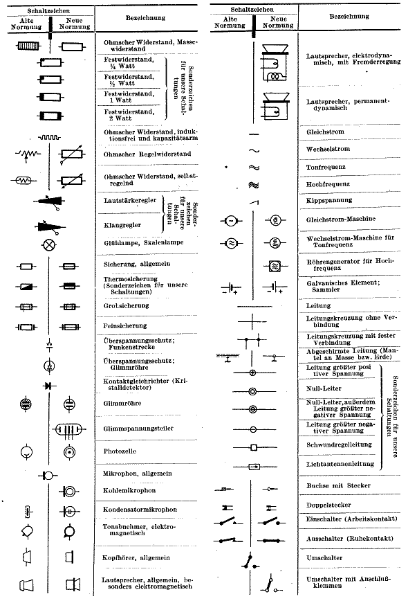
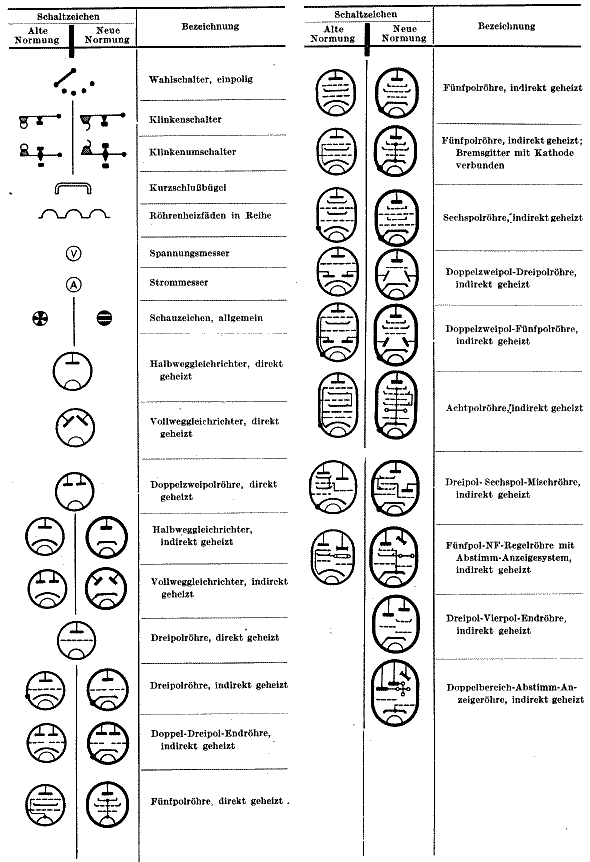
Hopefully, these symbols will help understanding pre war German schematics.
To thank the Author because you find the post helpful or well done.
Reading and Identifying Resistors
See this Article on physically identifying the resistors in the schematic.
(I moved it from here as this is too long and it's better separate)
To thank the Author because you find the post helpful or well done.
Working art Closes the Circle
Google theverge.com/2012/9/12/3319822/tube-map-radio-yuri-suzuki
Quoted extract
The famous design of the London Underground map was first conceived in the 1930s by engineering draftsman Harry Beck, who based his idea around the clarity and simplicity of electrical schematics — now, Japanese designer Yuri Suzuki has taken the concept full circle, creating a functioning radio using the Tube map as a circuit board. Currently on display at London's Design Museum, the printed circuit board (PCB) covers the full length and breadth of the city's present-day transport network, using strategically placed resistors, capacitors and other electrical components to harness the interconnections in the system. "I think the PCB is a remarkable invention," says Suzuki in an explanatory video. "Due to the process and efficiency of the electronics, you can see a really complex maze." His radio makes use of all 11 of the London Underground's lines, as well as the Overground and the Docklands Light Railway (DLR) — it even incorporates the Emirates Air Line, the new cable car system that runs 295 feet above the Thames in East London.
Google for article to see large photo
To thank the Author because you find the post helpful or well done.