Low-Frequency Radio Range
Low-Frequency Radio Range

The low-frequency radio range, also known as A-N radio range or four-course radio range, was one of the very early navigation systems. It was in use since 1929 and up to the sixties for marking both air and marine courses and guide aircraft or boats respectively to their airport or to the harbor. The system was based upon the emission of complementary Morse signals from an antenna system based upon two perpendicular Adcock antenna pairs. Four radiation lobs were generated, their intersections giving the wanted courses.
Generalized antenna system used in the LF radio range. Actually two transmitters, one keyed with A letter the second one keyed with N, fed two Adcock antenna systems. Adcock antenna system was derived from the rectangular loop type, widely used for its directivity in radio goniometry, suppressing the horizontal segments which gave no contribution to the directionality. Click to enlarge.
Depending upon the relative amplitude of the signals, angles of each course with respect to the others could be varied as in the two examples below.

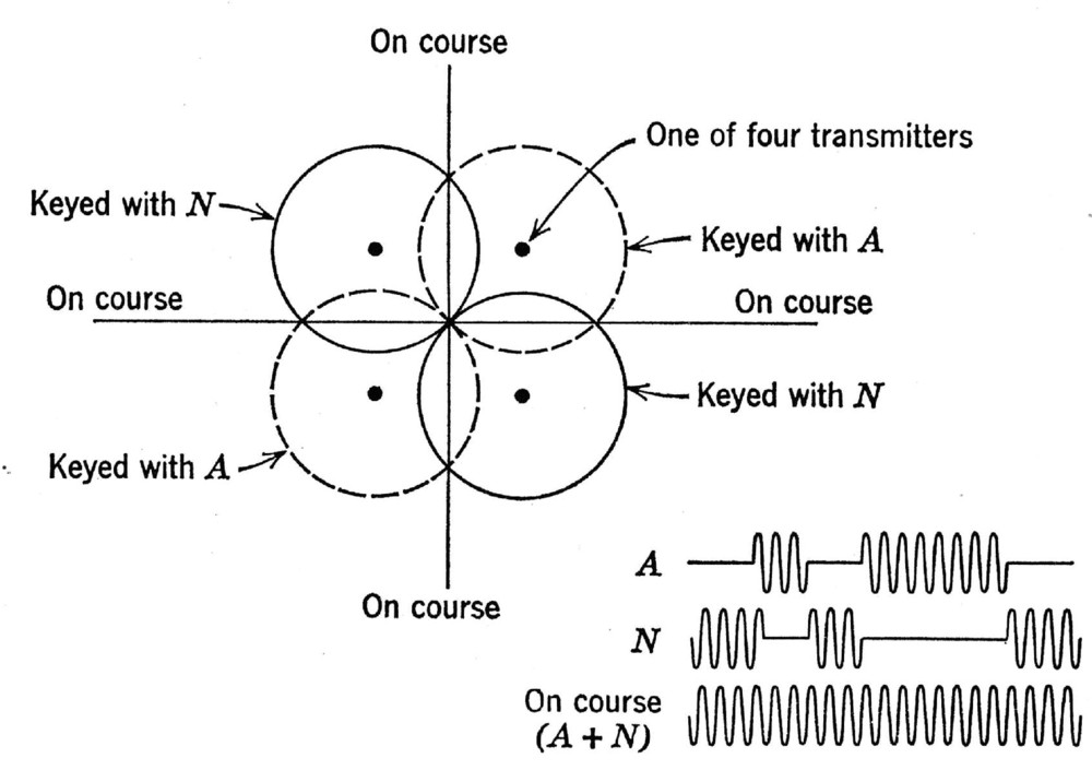
Polar diagrams for systems of two Adcock pair radiating antennas fed with different signals. Left, four perpendicular routes of continuous note are generated when both Adcock pairs are fed with signals of equal amplitude. Right, angles between routes can be modified feeding the two Adcock pairs with signals of different amplitude.
One Adcock pair was fed with a tone-modulated signal giving the ‘A’ Morse character, dot-dash, the second one emits the complementary ‘N’ character, dash-dot. When the pilot was straight in one of the four ranges, he could hear a continuous tone. Depending upon the course and the direction, if he moved to one side, he received the ‘N’ stream. On the contrary he could hear an ‘A’ stream when he moved to the opposite side. A fifth antenna in the middle of the array could be added to rotate the relative directions of the four ranges, by feeding with the proper amplitude and phase relations each of the other four ones. The fifth antenna tower was also used to transmit voice messages.
Frequencies assigned to the LR radio range system were in the long wave region of the spectrum. In America 65 channels spaced 3 kHz apart between 200 and 400 kHz were assigned to this service.
In some sets a visual indicator, based upon the vibration of two resonant reeds, gave information about the side and the magnitude of deviation from the route.
The LF radio range system was effective up to about 200 nautical miles, giving typical site error of 1º and instrument or sensitivity error of the same magnitude. Unfortunately propagation errors up to 25º could be observed beyond the horizon, due to sky-wave propagation and to interferences by remote stations. The system performance was also quite poor during thunderstorms.
Probably the LF radio range was the most used navigation system during WWII. In US about 100,000 LFR airborne receivers were still in active service in 1968. Here is one of the many very compact modular receivers build during WWII, the Detrola 43B.
Reference: Avionics Navigation Systems, M. Kayton and W.R. Fried
To thank the Author because you find the post helpful or well done.