Simple RF Buffer
Simple RF Buffer
Some frequency counters have both 50 Ohm or high impedance settings (often 1 M Ohm). However the probe coax cable will often change the frequency of the oscillator due to its capacitance. Using a 10:1 scope probe might still have too much capacitance and usually makes the signal level too low.
The solution is to temporarily add an FET buffer at the oscillator. Note that this solution on its own is no use for a live chassis. Add a 1:1 isolation transformer on the buffer output if the chassis is live. If total originality isn't needed then the circuit can be left in place.

The component values are not critical. R2 was picked to give about 2.5V DC on the FET Source. If R1 is too low the oscillator is loaded. If R1 is too high then there is more noise pickup and risk of self oscillation. The input connection must be very close to the oscillator output. Don't add coax at the input, only on the output. The output is fine terminated with 50 Ohm or 75 Ohm depending on the coax used. Use a 1 kV rated part for C1 33pF if there is HT. Otherwise any miniature ceramic capacitor will be fine. No need to use 1% resistors, that's just what I have in the drawers!
The circuit was tested from 100 KHz to 61 MHz.
Layout the stripboard with the output and input at opposite ends. Cut the tracks at the gate and source on opposite sides of the FET. I've made oscillators from 100 MHz to over 2 GHz using copper foil on top of stripboard and surface mount parts underneath, using a strip cut along the holes as a 1/3rd width stripline.
As current is about 5mA the 1N4148 diode is fine. Capacitors C1 to C3 are ceramic. C3 is because at HF & VHF the 470uF is a high impedance and thus the Drain would have RF.
An example layout.
In this case the input is an existing coax / screened cable removed from a socket. Plugging anything in to the original socket changed the frequency on the 25 MHz to 60 MHz band as well as the level, or even stopped the oscillator
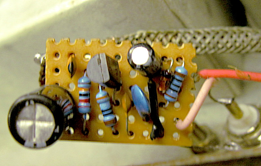

Input to the left. Output is pink wire, keep short or use coax. The red wire is 6.3 V AC.
Sometimes I use a 4.5 mm HSS drill-bit and other times I use a small plastic handle craft knife with the snap off disposible blades. Cut the tracks before soldering. Sketch layout on graph paper If you are inexperienced, either 0.1" or over 2 or 3 mm on metric.
I hate the modern solder. I'd love some 60/40 multicore fluxed stuff.
I use a magnifying lamp to check for solder bridges.
I may later run an LT spice simulation to discover what the input and output impedances really are. However, it doesn't perceptibly load the Advance E model 1 (EF50 oscillator) I tried it on.
To thank the Author because you find the post helpful or well done.