Sputnik - 9V Superheterodyne tube radio
Sputnik - 9V Superheterodyne tube radio

Fellow Radiophiles:
I have been studying Russian Subminiature Rod Tubes for a while. The unique structure of these tubes, which is based on electron-optic control of electron sheet beams originating in a capilary filament, confers them extraordinary performance and efficiency. These tubes were originally used only in Soviet military gear and were in use up until 1991 when the Soviet Union was dissolved. When these tubes became available on the commercial markets after their military obsolescence, a few hobbyists world-wide designed radios with them. RM member Dmitri Faguet from Kiev has investigated the history of these tubes and designed a very sophisticated dual conversion AM-SW Ham receiver along with other radio designs. Tohru Kawabata has a series of AM and FM radio designs with wide range of circuits and beautiful constructions. Vico Pichotka has designed and built a full stereo FM receiver in a very well finished assembly. It would be good to hear more about other designs with these Russian subminiature rod tubes.
I decided to continue this hobbyist tradition with my design of an AM-band (MW) superhet radio, but with the special condition that it operates from a 9V plate battery and 1.25V filament cell. The net value of Bplus is 9V+1.25V=10.25V because the 9V battery returns to the positive terminal of the 1.25V filament cell. I call this radio "Sputnik" for several reasons: Sputnik translates from the Russian to "satellite" or "fellow traveler", one of the first uses of these tubes was in the the transmitter on board the original "Sputnik" in 1957, had these tubes been allowed into the commercial market in the late 1950's, it is very likely that a consumer radio made with these tubes might have been called Sputnik.
The Architecture for a 9V Superheterodyne Tube Radio
The most difficult aspect of operating a tube radio from a 9V battery, while using tubes designed for plate and screen voltages around 45V, is to obtain nominal plate current flow, despite the 9V battery. Some of my solution to this problem is to operate the Local Oscillator of this Superheterodyne radio using the 1j37b (aka 1zh37b) in a Gammatron triode configuration as a DC-DC converter to power just the screens of the other tubes with +30VDC. The screens of these tubes are very efficient, requiring only about 5-10% of the plate current. It is also possible to bias these tubes to lower the plate current knee down to about +5V, thus making possible plate operation at +9V. Running the screens from 30VDC worked well for the small signal stages. The audio output stage required a pair of Gammatron triode configured 1j37b in push-pull to deliver 6mW to a very efficient 3"x5" speaker

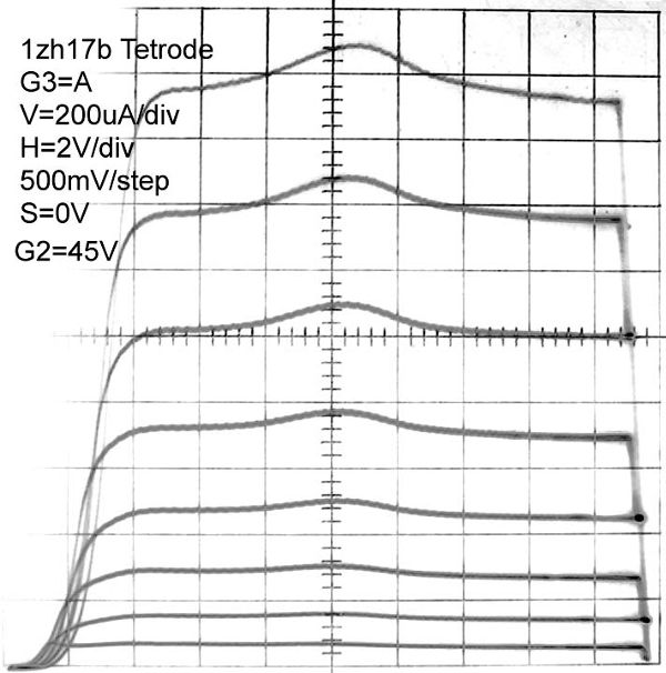
These photos show operation of the 1j17b in Pentode and Tetrode configuration. The DC bias at the suppressor grid G3 in pentode configuration shown on the left photo helps reduce the plate knee down to 3V when G3=+4V. This is very helpful to increase the available plate current swing from a 10.25V plate supply.
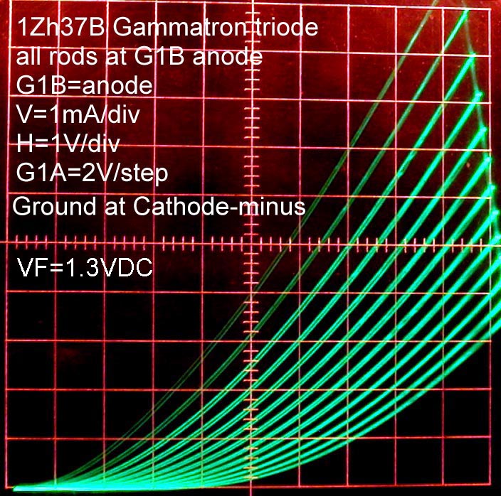
The Local-Oscillator/DC-DC-converter is based on a Gammatron/Gridless-Audion triode Hartley oscillator using the 1j37b, with it's two separate control grid rods operating as a control plate and an output plate. This kind of oscillator has a very high output conductance with just 9V at the control grid rod that serves for output, drawing up to 10mADC from 9VDC. I built a little AM transmitter based on the 1j37b in Gammatron/Gridless-Audion topology that swings 10Vp-p at the output control grid rod that is stepped up to 60Vp-p in the tapped tank circuit to drive the other low mu=0.35 control grid rod as input.
 While 30VDC at the screens and 10.25VDC(=9V+1.25V) at the plate worked well in the tuner section of this radio, more conductance was required of the output tubes that drive the speaker. The Gammatron, or Gridless-Audion, configuration was used again in the audio output stage to deliver 6mWrms to a very efficient speaker. It is surprising that I find myself turning the volume down from this 6mW output. The volume is comparable to that of a pocket transistor radio.
An alternative to the Gammatron triode configuration for conventional triodes, that also has very high conductance at low plate voltage, is the reverse configuration. In this case, the output terminal is the grid and the controlling element is the plate. This configuration has a lower transconductance and lower mu (reverse-mu=1/mu) than the conventional configuration with input at the grid and output at the plate, but it has much higher conductance.
The Circuit Blocks

The block diagram outlines a fairly conventional Superheterodyne conversion receiver with 455kHz IF, but with special consideration for 9mW of Screen power distributed at 30VDC*300uA from the local oscillator to the RF preamp, IF amp and audio push-pull preamp. All plates operate from 10.25VDC. There is a total of 9 Russian subminiature rod tubes The nominal current drain from the 9V battery is 21mA, and the filament current is 470mA from 1.25V. Operation up to 12VDC is fine, with a doubling of total output power to 12mW. Operation above 12VDC causes excessive wear in the Gammatron configured 1j37b in the Local Oscillator and audio output stages. Operation of the filaments from a 1.5V Alkaline D cell yields slightly more power and signal gain than from the 1.25V NiMH rechargeable D cell.
Full Schematics
Click the schematics to enlarge or save. The schematics are annotated with component values, measured bias levels and signal amplitudes.

The Gammatron/Gridless-Audion Local Oscillator:
The most difficult part of the design was the local oscillator. The topology was first developed for the 1.5V AM transmitter, but had to be improved here with a higher Q coil to deliver 10mW of total DC power for the RF, IF and Audio preamp Screens, and LO signal for Mixer screen injection. The final coil has a toroidal construction with a large 1.25" diameter and heavy gauge 18 solid enameled wire. The core material is Fair-Rite type 61 with initial permeability µ=125, and was chosen for the highest Q possible in the 1MHz range with small signals. The coil Q was measured at the end terminals as 140 at 120kHz in my Rohde&Schwarz BN6100, which extrapolates to over 1000 in the 1MHz to 2MHz local oscillator range. The low and high frequency losses of the tank circuit were carefully balanced to obtain a very flat 30VDC output with less than 1V variation over the tuning range. Much of this was done by trial and error. I measured several dozen manufactured coils and made a few dozen more coils myself. HF losses tend to be dominated with spurious capacitive loading that causes additional current on winding resistance. LF losses tend to be dominated by wire resistance.
The AGC control varies the current that is drawn on the +30V supply, This causes a variation on this supply up to +3V, and a frequency shift up to 2kHz from zero RF signal to the strongest local station. This shift is not objectionable because it falls well within the loop antenna bandwidth, and can be easily tuned out.

RF Preamp and Main AGC Control:
 The RF preamp contributes a voltage gain of 7x and isolates the local oscillator frequency that is present at the Mixer from the Ferrite Loopstick Antenna.
The plate load of this stage is untuned for ease of alignment. The very selective loopstick antenna with a Q over 100, provided adequate image rejection.
Copper foil over the tube reduces Miller capacitance coupling from the anode to the control grids. This reduces capacitive loading on the input tank circuit which eases alignment at the high end of the AM band. The reduced stray capacitance also reduces the effect of AGC on alignment that results when different gains multiply the Miller feedback capacitance by different amounts.
The plate is supplied with 9V from the battery, but the screen takes 30VDC from the Local Oscillator. The suppressor grid is biased at +4V to lower the plate knee down to 2V.
This stage performs the majority of the AGC control in the radio. Refer to the 1j37b gain curves for gm as a function of g1a and g1b control grid rods.
The Full agc voltage, up to -10V, is applied to g1a, while a smaller proportion of this voltage is applied to g1b. This results in an exponential control that is situated between very sharp cutoff and very remote cutoff, as seen in the 1j37b gain curves. The steepness of cutoff is arbitrarily controlled by the ratio of AGC signal applied to g1a and g1b. AGCL is controlled with a pot as a fraction of AGC.
The following shows how various proportions of AGC and AGCL affect the overall AGC response of the radio. AGC action for the 6 tube RCA RC1140 was plotted for comparison. The very remote cutoff characteristics of the tubes in the RCA are shown in the magenta curve, and resulted in a softer AGC action. The sensitivity for Sputnik is also substantially higher in the final AGC configuration, as can be seen in the 10uV response in the Blue curve. The final AGC configuration yielded a compression of the 60dB range from 100uVrms to 100mVrms at the RF grid, into a 7dB output range. There was no distortion for RF signals at the antenna up to 1Vp-p.
The plate current of the RF, Mixer and IF stages, which are all under AGC control drive a signal strength meter.

Tetrode Mixer with Screen Injection:
 The mixer stage is configured as a tetrode mixer with 57Vp-p screen injection swinging +/-28.5V above and below the 10.25V rail. This is the most efficient Local Oscillator injection choice, considering that the Local Oscillator would have to drive the Screen with a DC bias, if another method of injection was used.
This stage contributes a gain up to 30X.
The tetrode configuration resulted in a slightly higher gain than the pentode configuration with a fixed bias at G3.
This stage has different frequencies at every terminal, so shielding was not deemed necessary to reduce anode to G1 capacitance because the IF transformer load prevents feedback at RF frequencies.
A 1pF cap was added across the IF transformer to increase over-coupling to help flatten the IF frequency response.
The control grid get's it's bias from AGCLO via the R16=10Meg. This helps center the congrol grid bias in the center of the linear range for the strongest signals, while running the stage at top gain under weak signal conditions.
IF Amplifier with Bias Control:
 This fairly conventional IF stage contributes up to 58x voltage gain.
A tight copper foil shield surrounding the tube is necessary to insure the lowest possible Miller feedback capacitance from the plate to the control grid. This capacitance was measured as 0.008pF. If the shield is removed, the plate-g1 Miller feedback capacitance increases to 0.05pF and causes oscillations. See Felix Shaffhauser's calculation of the reflected impedance of the inductive plate load to the grid due to Miller feedback capacitance.
The IF transformers were chosen from what I had in my collection. Their internal impedance of 300kΩ is what is often found in American AC/DC tube radios. The 300k resistors at the IF transformers are not explicit; the represent the measured winding losses. A higher impedance, approaching 1Meg, at resonance, would have increased the gain of the IF and Mixer stages. A higher impedance transformer might be found in a sensitive commercial battery tube radio. I also had a salvaged Grundig FM/AM IF transformer with a measured 600kΩ internal impedance, but it was too big to fit in the allotted space.
The plate voltage is 10.25VDC from the battery, while the screen gets it's 30VDC from the Local Oscillator. The 4V positive bias at G3 is essential to keep the plate knee below +3, thus allowing a plate swing around the 10.25V DC plate voltage, up to 14V p-p without clipping. The overall AGC loop insures that this level is never reached. The 4V bias source is also shared by the suppressor grid G3 of the pentode RF stage.
The control grid G1A+G1B gets a small portion of the overall AGC control voltage at AGCL to move the G1 bias point slightly negative under strong signal conditions. This small change in G1 bias affects gain by less than 50%. A small fixed negative bias might have been used, but this gives just a bit more maximum gain for small signal conditions. Earlier versions of the AGC control had different voltages applied to G1A and G1B, as is done with the RF stage, but as the AGC plots show above, this approach did not produce as much AGC compression as running the Mixer and IF stages near full gain, while applying agressive AGC control to the RF stage. The 1j17b tube might have been used here because it is identical to the 1j37b, but with G1A and G1B wired together as one grid.
AGC Detector and Complementary Audio Detectors:
 Separate detectors recover audio and AGC voltages.
There are two audio detectors to accomplish phase inversion to drive the push-pull audio preamp. The 20us time constant of the detector load including the 1Meg volume control load is fast enough to track the audio envelope, while attenuating the 455kHz IF frequencies by 50x (-34dB). A second ripple filter did not seem necessary, as there were no objectionable "birdie" types of feedback from the IF harmonics to the input, even at 910kHz.
The AGC voltage is derived with a voltage doubler from the plate of the IF stage, before the 0.75 signal loss across the output IF transformer. The frequency response at the plate is also sharper because it has not benefitted from the bandwidth flattening effect of the critically coupled secondary. This makes for sharper tuning.
A voltage doubler works as an AGC amplifier with a gain of 2 and, more importantly, regulates the IF plate swing to no more than 10Vp-p with 1Vp-p of input at the Ferrite Loopstick antenna.
Two AGC voltage levels are generated. The full value is at AGC and is the primary gain control for the RF stage. AGCL is a small grid bias adjustment for the Mixer and IF stages. The 2MEG pot controlling AGCL was used for AGC experimentation, but could now be replaced with a 1.5Meg and 470k resistors.
The final AGC configuration yielded a compression of the 60dB range from 100uVrms to 100mVrms at the RF grid, into a 7dB output range. There was no distortion for RF signals at the antenna up to 1Vp-p. See the measured AGC curves above. The total maximum gain from the Ferrite Loopstick Antenna to the IF plate is 86dB=20000.
Push-Pull Audio Preamp:
 The audio preamp was the last stage to be designed, but it still was quite challenging, because it provides 72Vp-p of differential drive to the audio power output push-pull Gammatron stage.
I designed this stage after I became aware of the extraordinary efficiency of the 1j24b, after RM member Dmitri Faguet showed me his radio designs with this tube.
The separate volume controls were necessary to control the complementary signals provided by the detector. These tubes also have the advantage of having negligible control grid G1 conduction for inputs up to +1V. This explains the grounded grid bias.
The tetrode configuration provided just a little more drive than pentode configuration. The plate operates from the 9V battery with 10.25V above ground. The screens get their 30VDC bias from the Local Oscillator.
A high impedance 1:3 plate transformer steps up the 12Vp-p that is developed at each plate to 36Vp-p at each of the two Gammatron grids of the audio power amplifier, for a total of 72Vp-p differentially.
Push-Pull Gammatron Triode Audio Output Amplifier:
 The audio output power stage required the added conductance that only a Gammatron configured 1j37b can provide from a 10.25VDC power supply. (An alternative high conductance connection with conventionally gridded tubes, is reverse triode operation with the input at the plate and the output at the grid)
The low mu=0.4 and low gm=750uS in this configuration requires up to 72Vp-p of differential drive at the Gammatron input control rods.
The output transformer was carefully chosen for good impedance match to maximize power delivery to the 6Ω 3"x5"speaker. A 1k:8Ω center tapped hobby transformer with a 10:1 turns ratio turned out to be a lucky fit.
An external -20V bias is derived from the local oscillator to keep the nominal plate current at 5.8mA per tube. The current swing at each tube is 9mAp-p, while the voltage swing at each plate is an undistorted 3Vp-p.
There is a very unusual variable capacitor at C1. This variable capacitor is necessary to balance the input transformer parasitics to insure equal swings at each Gammatron input. C1 is adjusted to minimize distortion at the output with a full scale sinewave. The value of C1 will vary from transformer to transformer and may be needed on the opposite winding terminal, instead. A filter capacitor at the center tap of the drive winding would also have insured perfect symmetry in the Gammatron input drive.
However, the "floating" 20Meg drive to the center tap of the drive transformer was chosen to make it possible to implement grid leak bias from 0V when the 20Meg resistor is optionally grounded. Under this grid leak bias mode the average gain of the output stage is increased at the expense of doubled nominal plate drain to 10mA per tube. The voltage swings at the drive transformer secondary are such that whichever of the two winding terminals is most positive stays gently biased near ground, while the opposite terminal swings negative. This can be understood as a reverse form of Class AB operation, where maximum current occurs under zero signal conditions and audio signals reduce drive to each tube in alternate half cycles. The voltage at each plate appears distorted, in a half-wave rectified form, but they are combined into a clean signal at the speaker. The 1mA meter movement has a 1R3 shunt to increase it's range to 25mA and is wired in series with the 9V battery to show a fixed audio supply current with -20V bias, but will show a strongly varying current when the bias is 0V, as a VU meter, and is also a good indicator of battery charge.
The 0V grid leak bias and the -20V bias deliver the same maximum undistorted (<10%) RMS power of 6mW into the 3"x5" speaker. The 0V grid leak bias has twice the gain of the -20V bias level.
Developmental Breadboard Construction
This project was my most challenging hobby project so far. This explains the "breadboard" construction with plenty of open space for experimentation and for easy changes. The tin on the right houses the most efficient 3"x5" speaker in my collection. It has a gentle 200Hz resonance and was a very convenient, if not humorous, fit for the speaker. The small board to the left is a simple solid state regulated DC power supply and battery charger. The Ferrite loopstick antenna sits about 10" above the board on a pivoted support. The wire seen threaded down the left of the antenna post is the active feed from the loopstick. The main portion of the antenna coil is shielded from E-field interference with brass rods. The smaller coil at the right of the Ferrite is in series with the main coil and is grounded. This small coil has a loose fit with a piece of card board to hold the RF alignment at the low end of the AM band.
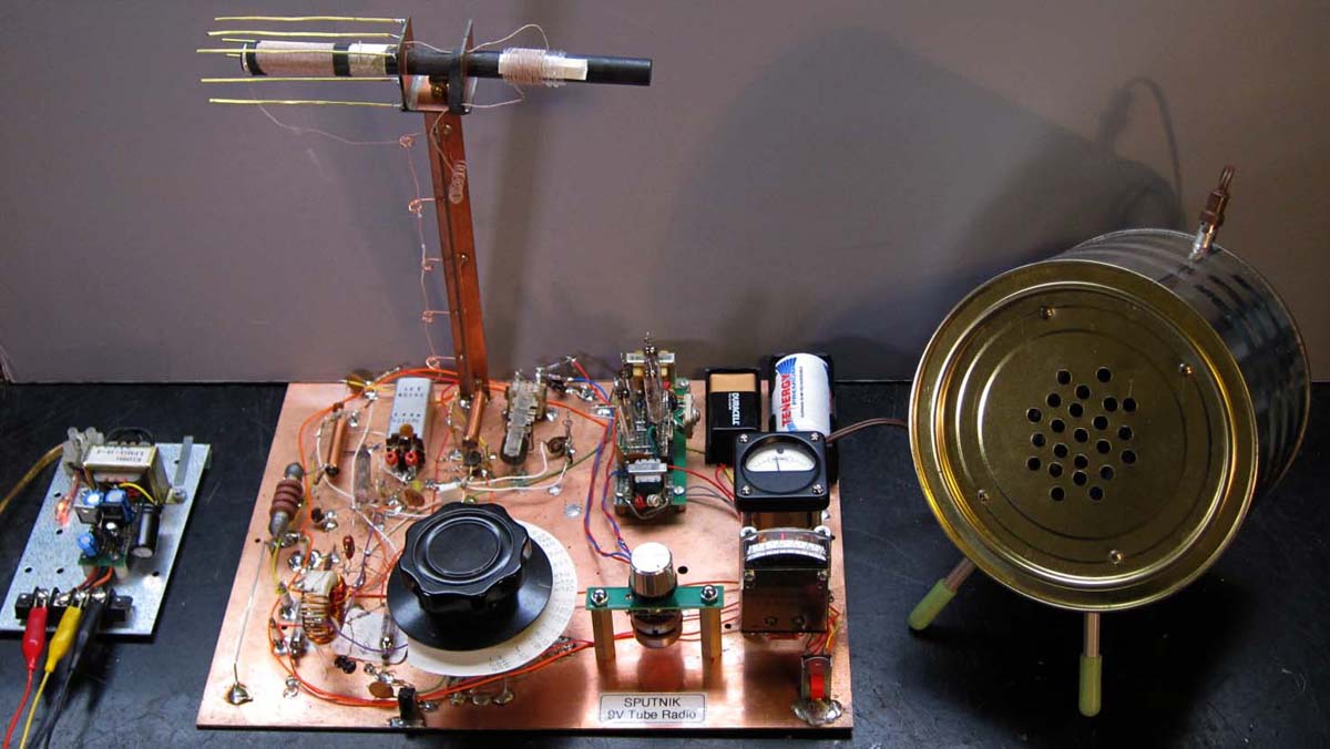
Click photos to see finer details.


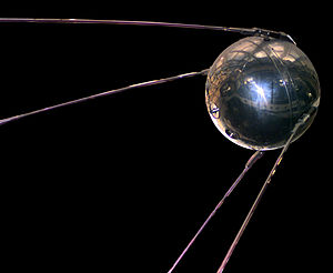
The 1957 Fellow Traveler "Sputnik-1" Satellite as shown in wikipedia.
Best regards,
-Joe
Attachments:- sputnik_blocks1.gif (14 KB)
- 1zh37b_1zh24b_audio_vol.gif (16 KB)
- sputnik_gammatron_1zh37b_lo_and_mixer_if_agc_rf_ppdet_vol.gif (56 KB)
- sputnik_lo.gif (17 KB)
- agc_rf_agcl_rf_mix_if1.gif (26 KB)
- sputnik_9v_tube_radio_speaker_charger.jpg (108 KB)
- sputnik_9v_tube_radio_front.jpg (94 KB)
- sputnik_9v_tube_radio_labelled.jpg (198 KB)
To thank the Author because you find the post helpful or well done.