telefunken concertino 6 i need help on the power supply
? telefunken concertino 6 i need help on the power supply
hello to all members , thanks again for the help to determinate the correct model , on the first look detect changes on the power supply (cams from same old technician) , this guy cut the AC selector ( 240v ,220v ,150v ,125v ,110v ) of the radio and the original AEG B 300 C 75 diode... .
As replacement diode use the B280C 800Si ( old technician replacement not my choice. )
Before plug the radio again to my country power source ( 230v ), remove all tubs of the radio and measure the high voltage on the pins 7 and 9 of EL84 tube, pin 9 give me 350v dc pin 7 give me 340v dc .The original schematic have on pin 7 250v dc and on pin 9 230v dc . Hear i need help, how to tune the voltage of the power supply with the correct voltage , please give me advice ,is very important to me on my country is very hard to find a specialist to repair the radio .
Photos of transformer and the diode :
![]()
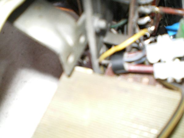
Thanks very mach
To thank the Author because you find the post helpful or well done.
No load voltage

You are just measuring the no load voltage. More or less this is near to the peak value of AC secondary voltage. No worry, put the tubes back into their sockets and measure the voltage after about 20 seconds from the power-up.
Measure the grid bias of the EL84. You should find about - 7.3 volts from G1, pin 2, to cathode, pin 3.
Best wishes,
Emilio
To thank the Author because you find the post helpful or well done.
load measure
Thanks Mr.Emilio so so mach , pin 2 to pin3 after 20 sec came - 5.1 volts ( the voice is on lower point like to my tube amplifier if make bias regulation.) , if the time is run more step down by one m.volt. Also measure and the B+ on the load : pin 7 =251v dc - 244v dc pin 9 = 278v dc - 271v dc. All is ok ? can operate this radio with no problems to damage the raidio ?
Thanks again for the help Mr. Emilio .
To thank the Author because you find the post helpful or well done.
Leaky C55
If the EL84 starts with about -5 volts grid bias, then C55, 22nF, is somewhat leaky and must be replaced. To be sure, pull out the EL84 from its socket and measure the voltage from pin 2 and chassis with a high-impedance voltmeter: you should measure zero. Any positive voltage indicates leakage through C22. A polyester film capacitor will be fine.
Remember that a wrong grid bias overheats the EL84, shortening its life.
Emilio
To thank the Author because you find the post helpful or well done.
C55 replaced and new measure
hello Mr. Emilio, thank you again very very mach for your support and for your fast answer, replace the C55 , 22nf 500v dc (original capacitor) with 22nf capacitor 400volt, also i have and photo to see if the type is good for this job (never trust my self choice, no have the experience to have you!).

After the replacement capacitor pull out the EL84 tube, power up the radio and measure the voltage from pin 2 and chassis, starts with negative voltage and 5 sec later the readings going to the 0, wait 1 min and power off the radio, the capacitor C22, 4.000 pf looking healthy. Also measure the grid bias again and yes 20 sec later start with - 7,20 volt dc :-) , one question please about of the grid bias, if wait more than 20 sec, the grid bias start to going down again, on 2 - 5 min around give me the value of - 1,20v dc on the KW ( shortwave ) band and power down the radio to be sure is normal ?
One more please, no have a high-impedance voltmeter and find this schematic on this web allaboutcircuits.com/vol_6/chpt_6/5.html page and plan to make one for this cases, need your valuable advise if is good to construct this one ? or if you have any advise is welcome.
big thanks again for your time and wait the next inspection orders first, before operate normal this radio.
Thanks again
Best regards Pantelis.
To thank the Author because you find the post helpful or well done.
Possible causes
Dear Pantelis,
I guess that, when the grid bias falls toward zero, even the sound decreases. Anyway, since the grid bias voltage should remain around -7.3 volts even after the warm-up, you should further investigate around the EL84 biasing. Remove the cathode capacitor, I read C61 but not sure, 100uF. Connect the voltmeter across the cathode resistor W36, 120 ohms. It should start reading 7.2 volts after warm-up. Observe if the reading increases, decreases or stays steady over time. If the voltage drops toward zero in a short while, the EL84 must be replaced. If the voltage increases over than the starting 7.2 value, this means that the new C55 is still leaky. If the voltage remanis steady at 7.2 volts, then probably the cathode capacitor C61 was shorted.
The circuit found for high impedance voltage measurements is fine. Just add a series resistor to probe, 10K to 100Kohms would be fine, to protect the op-amp input pin against possible overvoltages.
Emilio
To thank the Author because you find the post helpful or well done.
new readings
hello Mr. Emilio, thank you very mach for all.
I have allready ordered the new unused tubes(from stock market) for this radio but to receive the order in my country takes about a month.I think it's better to wait to receive the order before starting the new readings cause i don't have a tube tester.I 'm a little bit worried to continue the readings tests with a possible sort circuit tube on the radio.I hope to receive the new tubes soon and start the readings again.
Thanks again,
Best regards Pantelis.
To thank the Author because you find the post helpful or well done.
new tubes and new readings
Hello Mr. Emilio, thank you very mach for everything, to day receive the new tubs EL84, ECH81, ECC85 and the EM80 the eye tube.
After the tube replacement good news, the grid bias stop to step down to the 0 and now is stable on : -7,7v dc this indicates the old el84 make the drop voltage, also the eye tube work again ,the FM band work also, the radio is full factional now and all bands looking good .
Now the problem is the load voltage,i measure again the B+ after the diode on load is : 312 v dc after 3 min and don't step down ... also the em80 on pin 9 take 275v dc and the normal values is 270v dc for B+ and 230v dc on pin 9 of the eye tube , after 10 min of test the transformer start to get hot ... and close the radio before is to late for the tubs ....
Please i need your advise if you have time, how to solve this new problem ?
Thanks for your time Mr. Emilio,
Best regards Pantelis.
To thank the Author because you find the post helpful or well done.
Supply section
Dear Pantelis,
voltage values look acceptable. Some moderate heating of the power transformer after several minutes of operation can be normal. In other words, do not worry if the transformer becomes warm. You may suspect a serious problem if it becomes hot, with an appreciable smell of overheated paper and varnish. Anyway I understand that the B+ voltage remains stable, so probably you do not have serious problems. If the new rectifier is still selenium, you should check the reverse resistance of diodes: when the leakage current is high even the rectifier itself becomes hot. The most probable cause of overheating can be a short circuit or a leakage inside one of the windings of the transformer. You say that the supply section of the radio had been serviced and the original rectifier had been replaced. I suspect that the old faulty rectifier caused an overheating of the transformer windings and now the insulating paper layers could be partially carbonized. But in this case you must sense a quite intense smell, with a remarkable drop in the B+ voltage.
Best wishes,
Emilio
To thank the Author because you find the post helpful or well done.
Grid emission

Obviously your old EL84 has grid emission. Details can be seen here, but unfortunately in German. The problem is quite common in EL84. The grid becomes hot after few minutes and the temperature is sufficient to cause an emisson of electrons from the grid. Even if your grid condenser is o.k. the grid bias starts to become more and more positive due to the elctrons which leave the grid. As a result the anode current increases and the valves becomes more hot and also the grid etc. etc. On a valve tester these valves are tested good because the effect starts after a few minutes when the grid becomes hot.
If your grid condenser has a leakage the grid bias will be to high direct after switsching on the set.
If you are concerned about your transformer control the overall current of the set. It should be 250 - 300 mA AC corresponding to 55 Watts.
The fuse should also be in the right range of 300 mA.
Best regards
Rüdiger Walz
To thank the Author because you find the post helpful or well done.
I would rather say no emission at all
I might be wrong of course, but I guess that the problem in the old EL84 was just a poor cathode emission. The tube was certainly operated at saturation for a long while, due to the wrong bias caused by the leaky capacitor. Probably the oxide layer was all stripped away. Of course the overheated tube became gassy, with iridescent getter, and then some grid current may be found.
In this case, the grid bias is given by the voltage across the cathode resistor. The bias may vary due to a possible drop across the grid resistor, it is true, but here we found that the cathode voltage was dropping toward zero in a short while. I am not a physicist, but it is hard to believe that the grid emission shadows and replaces almost entirely the cathode emission. Should such a phaenomenon rise up, we must expect an increase of the current flowing in the tube and then an increase in the voltage drop across the cathode resistor. The current flow through the control grid is anyway limited by the external grid resistor.
I guess that a sustained secondary emission might only appear as consequence of a huge electron flow inside the tube. If we read only about 1 volt across the 120 ohms cathode resistor, than the total current in the tube is in the order of 10 milliamps and I do not believe that such a low value could trigger or sustain any relevant secondary emission flow.
Emilio
To thank the Author because you find the post helpful or well done.
Yes, you are right
I am sorry , I misread the report about the grid bias. When talking about grid bias I thought he was measuring at the grid directly, but obviously at the cathode, which is a positive voltage. If this is too low, there is no emission.
Nevertheless he reported that B+ at the anode was 250 - 244 V which shows that the tube provides enough emission, but with a leaky grid condenser in the wrong part of the charakteristic.
The grid emission simply can be tested by measuring at the grid. With a good grid condenser the grid voltage should be 0 V dc against chassis and the cathode voltage will stay constant at + 7.5 V against chassis. With grid emission the grid voltage will be > 0V and cathode voltage will increase slowly > 7.5 V, also anode voltage drop will increase.
I experienced more grid emission problems with the EL84 than low emission problems, so I expected the same here.
Best regards
Rüdiger
To thank the Author because you find the post helpful or well done.
The raidio look Good
I took all the measurements again , been using the radio up to 2 h. with my multimeter connected, no drop voltage , all bands work perfect and the tuner is super sensitive if i compare with my other radios ,the grid bias is stable, on fm band gives - 7,35v dc and the shortwave band give me -7,56v dc, looks to be working good now ,thank you very much Mr.Emilio and Mr.Rüdiger , with your best help the radio came back to life again, many thanks again for the support with good information and your experience.
Now is my turn to help, i have 4 boxes full with resistors of different ohms, up to 1W given by an old friend. If anyone needs any let me know so i can help also.
Best regards, Pantelis
To thank the Author because you find the post helpful or well done.