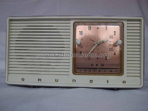
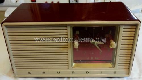
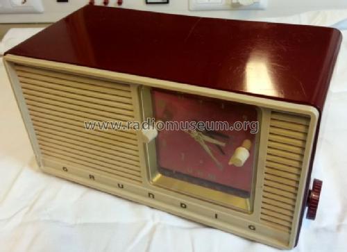
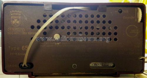
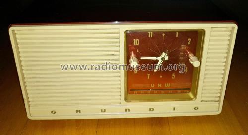
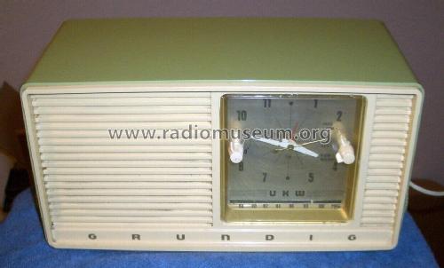
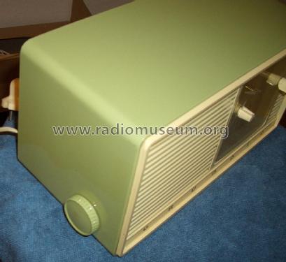
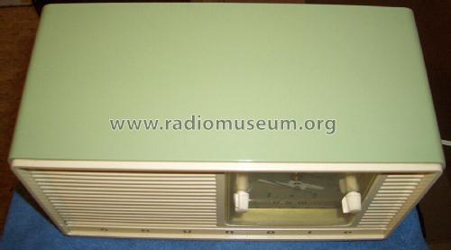
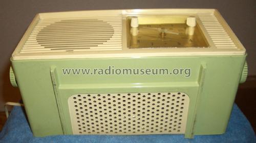
Musikgerät 65
Grundig (Radio-Vertrieb, RVF, Radiowerke)
- País
- Alemania
- Fabricante / Marca
- Grundig (Radio-Vertrieb, RVF, Radiowerke)
- Año
- 1958/1959
- Categoría
- Radio - o Sintonizador pasado WW2
- Radiomuseum.org ID
- 21670
-
- alternative name: Grundig Portugal || Grundig USA / Lextronix
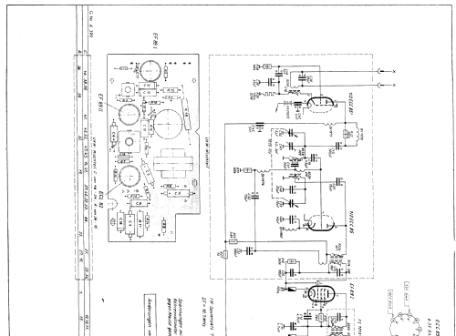
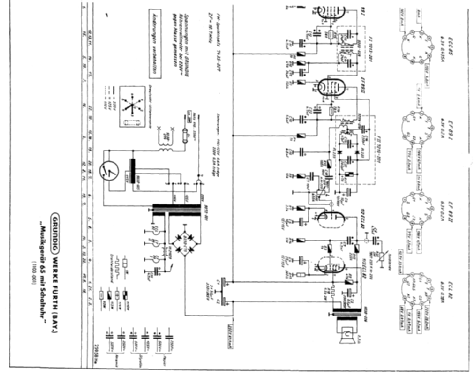


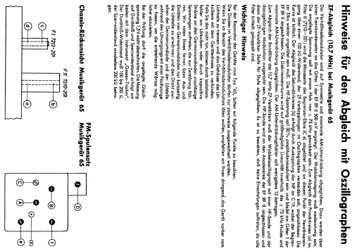

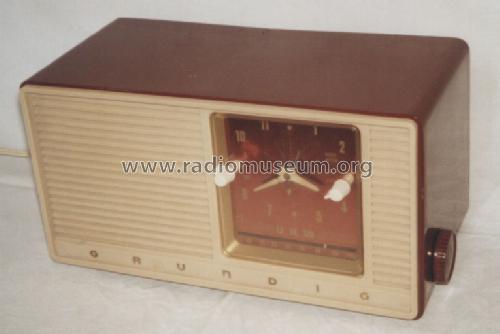
Foto selbst erstellt

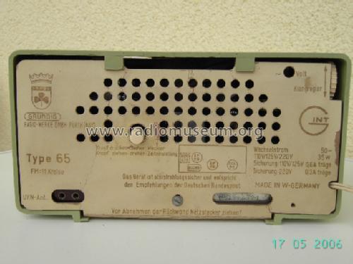
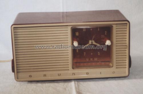
Foto selbst erstellt
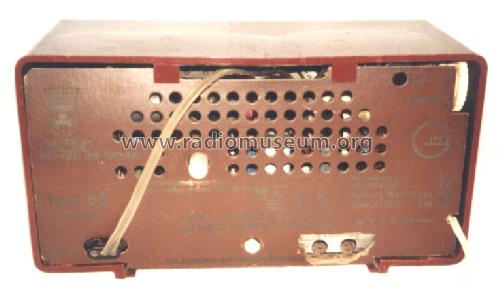
Foto selbst erstellt
Sammlung
Sammlung

Sammlung
Sammlung
Sammlung
eBay item number:195561565536

eBay item number:195561565536
eBay item number:195561565536

eBay item number:195561565536
eBay item number:195561565536
eBay item number:195561565536
eBay item number:195561565536
Haga clic en la miniatura esquemática para solicitarlo como documento gratuito.
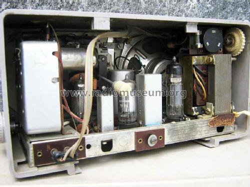
- Numero de valvulas
- 4
- Numero de transistores
- Principio principal
- Superheterodino con paso previo de RF; ZF/IF 10700 kHz
- Número de circuitos sintonía
- 9 Circuíto(s) FM
- Gama de ondas
- Solamente FM
- Tensión de funcionamiento
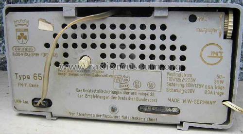
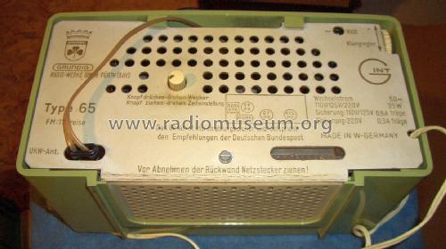
- Red: Corriente alterna (CA, Inglés = AC) / 110; 125; 220 Volt
- Altavoz
- Altavoz dinámico (de imán permanente) / Ø 11 cm = 4.3 inch
- Potencia de salida
- 2.5 W (unknown quality)
- Material
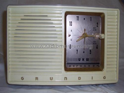
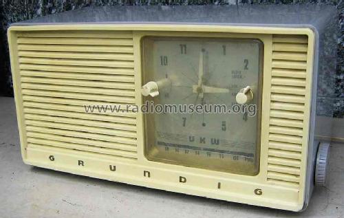
- Plástico moderno (Nunca bakelita o catalina)
- de Radiomuseum.org
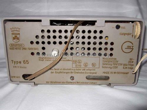
- Modelo: Musikgerät 65 - Grundig Radio-Vertrieb, RVF,
- Forma
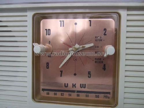
- Sobremesa con reloj o Radio despertador.
- Ancho, altura, profundidad
- 280 x 150 x 140 mm / 11 x 5.9 x 5.5 inch
- Anotaciones
- 2 Germanium-Dioden RL233 im Ratiodetektor.
VDRG-Handbuch 1958/59 und Geräte-Rückwand nennen 11 Kreise, dies ist falsch.
- Peso neto
- 3.6 kg / 7 lb 14.9 oz (7.93 lb)
- Ext. procedencia de los datos
- Erb
- Procedencia de los datos
- HdB d.Rdf-& Ferns-GrH 1958/59
- Otros modelos
-
Donde encontrará 6196 modelos, 5420 con imágenes y 4190 con esquemas.
Ir al listado general de Grundig (Radio-Vertrieb, RVF, Radiowerke)
Colecciones
El modelo Musikgerät es parte de las colecciones de los siguientes miembros.
Contribuciones en el Foro acerca de este modelo: Grundig Radio-: Musikgerät 65
Hilos: 2 | Mensajes: 5
Momentan restauriere ich eine kleine Grundig 65. Eine wirkliche Fummelei bei diesem Winzling! U.a. muss ich noch ein neues Plexiglas für die Uhr einarbeiten. Das Originale ist leider blind und hat Risse.
Dabei stellt sich mir die Frage, wie die Funktionen der Uhr und des Weckers im einzelnen sind. Eine Bedienungsanleitung habe ich leider im Internet nicht finden können.
Hinweis: Der R19 (Drahwiderstand) ist bei diesem Modell ein Schwachpunkt. Er hatte keinen Durchlass mehr.
Nette Grüße
Norbert Meyer
Norbert Meyer, 26.Sep.17
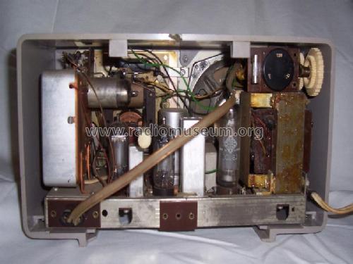
Grundig 65 disassembly instructions:
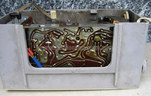
- Remove single large screw at lower center of the back. This allows you to gently pull the whole back straight out and off.
- Using a long screwdriver (M4) reach in outside and along each side of the chassis and find the set screws securing the side knobs for station tuning and volume. These knobs does not pull nor screw off. You may have to turn the knobs to locate the screwheads.
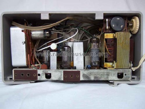
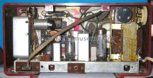
- Remove all four valves.
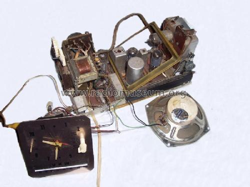
- Reach in using a small soldering iron and disconnect the speaker connections at the speaker terminals. The speaker wires are embedded in the output transformer at the other end, so this is the only way.
- In similar fashion disconnect the three wires going to the synchronous clock mechanism.
- Again using a long, thin screwdriver reach in below the chassis and locate the pair of screws connecting the chassis to the front of the cabinet. On my radio these screws were hidden behind the green wire bundle running along the front of the chassis.
- The chassis can now easily be pulled out of the cabinet, providing access to all components.
*) There are some hidden paper- and electrolytic capacitors below the mains transformer. In particular the critical DC blocking cap C9 is there. So the mains transformer needs to be temporary disconnected and removed to properly service the radio.
*) It is tempting to turn the chassis upside down during service, resting it on the top of the VHF tuner and the mains transformer assembly. Careful though! The heater supply feedthrough capacitor, C42, for the VHF tuner is very long and it is very easy to break it when the chassis is resting upside down. This had happened to my radio during a previous (failed and very crude) repair attempt and I had to break out the 100W soldering iron to replace this capacitor with a suitable replacement. Fortunately a low voltage (and thus physically shorter) feedthrough cap will serve nicely here, somewhat preventing the problem from occuring again.
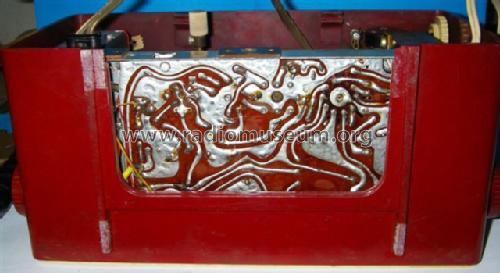
*) My clock radio have what I can only describe as a factory original mechanical manufacturing error?! The main power supply bridge rectifier, B250-C75, had apparently been displaced from its intended location, complete with original long AC supply wires from the transformer. There are a pair of M3 threaded holes in the chassis, which are obviously intended for mounting the bridge rectifier. However if one attempts to do so, the bridge will conflict with and hit the screwheads holding the dial cord tensioning device in place. Oops.
As a result on my radio someone at the factory had attempted to move the rectifier up and away from the front, using a hole intended for mounting the VHF tuner unit plus a spare elongated hole instead. This worked fairly OK, except that one was then unable to reach from below the fourth screwhead securing the Aluminum cover of the VHF tuner unit.
The fix for me was to use the correct threaded mounting holes by adding 10x M3 flat washers as spacers, allowing the bridge rectifier to ride clear of the conflicting screwheads. I also had to add a new M3 screw to secure the VHF tuner. Everything now makes much more sense. For instance the short, red piece of flex tubing covering the B+ terminal on the rectifier is now obviously there to prevent an accidental short between the B+ terminal and the grounded screen wire of the IF connection coming from the VHF tuner.
Frank Nicholaisen, 10.Feb.07