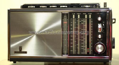
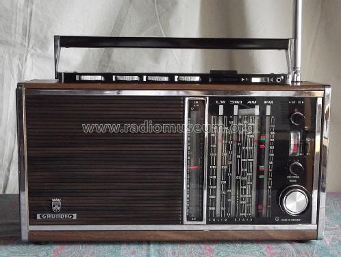
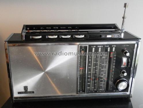
Satellit Transistor 6001 Skala ohne Sendernamen
Grundig (Radio-Vertrieb, RVF, Radiowerke)
- País
- Alemania
- Fabricante / Marca
- Grundig (Radio-Vertrieb, RVF, Radiowerke)
- Año
- 1969–1971
- Categoría
- Radio - o Sintonizador pasado WW2
- Radiomuseum.org ID
- 2231
-
- alternative name: Grundig Portugal || Grundig USA / Lextronix


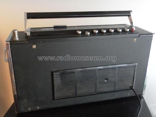
This one of my best Sattelit. It is NEW!!


Haga clic en la miniatura esquemática para solicitarlo como documento gratuito.
- Numero de transistores
- 21
- Principio principal
- Superheterodino doble o triple conversión; ZF/IF 1850/460//10700 kHz; 2 Etapas de AF
- Número de circuitos sintonía
- 13 Circuíto(s) FM
- Gama de ondas
- OM, OL, más de dos OC y FM
- Tensión de funcionamiento
- Pilas / 6 × 1,5 Volt
- Altavoz
- 2 Altavoces
- Potencia de salida
- 2 W (unknown quality)
- Material
- Cuero/Tela/ Plástico sobre otros materiales
- de Radiomuseum.org
- Modelo: Satellit Transistor 6001 [Skala ohne Sendernamen] - Grundig Radio-Vertrieb, RVF,
- Forma
- Portátil > 20 cm (sin la necesidad de una red)
- Ancho, altura, profundidad
- 440 x 260 x 120 mm / 17.3 x 10.2 x 4.7 inch
- Anotaciones
-
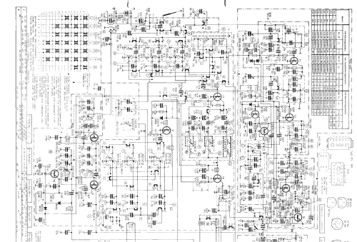
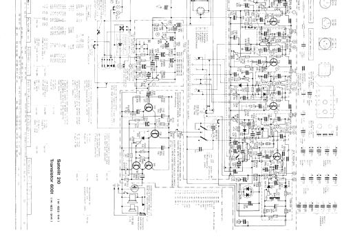
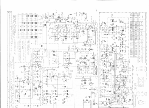
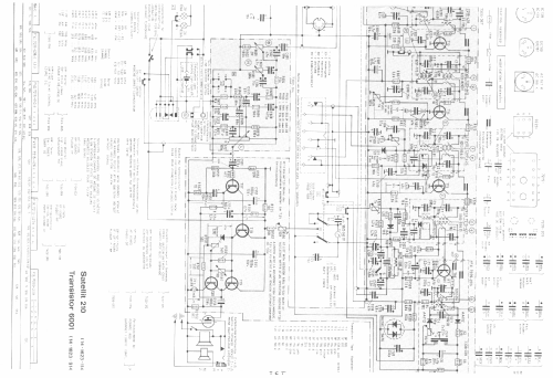
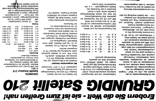
Skala ohne Sendernamen.
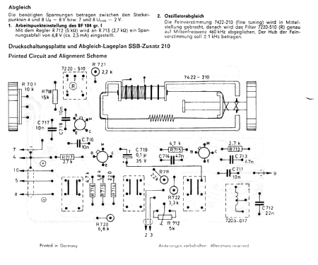
14 Kurzwellen-Bereiche, Langwelle bis 420 kHz; AFC und FET-Mischer für UKW; Feldstärke-Anzeige; KW = Doppelsuper; Anschluss an 6-V- bzw. 12-V-Autobatterie über entsprechendes Autobatteriekabel; Netzbetrieb mit eingesetztem, herausnehmbaren Netzteil oder Betrieb aus dryfit-PC-Akku und Netzteil TN14 möglich.
Siehe auch Satellit 210 Transistor 6001.
Anschluß für den SSB-Zusatz 2000.
Jeder Transistor-Typ nur einmal gelistet.
- Peso neto
- 6.7 kg / 14 lb 12.1 oz (14.758 lb)
- Procedencia de los datos
- Handbuch VDRG 1969/1970 / Radiokatalog Band 1, Ernst Erb
- Documentación / Esquemas (1)
- -- Original-techn. papers.
- Otros modelos
-
Donde encontrará 6196 modelos, 5420 con imágenes y 4191 con esquemas.
Ir al listado general de Grundig (Radio-Vertrieb, RVF, Radiowerke)
Colecciones
El modelo Satellit es parte de las colecciones de los siguientes miembros.
Contribuciones en el Foro acerca de este modelo: Grundig Radio-: Satellit Transistor 6001
Hilos: 4 | Mensajes: 25
Guglielmo Russo, 05.Nov.15
Hi!
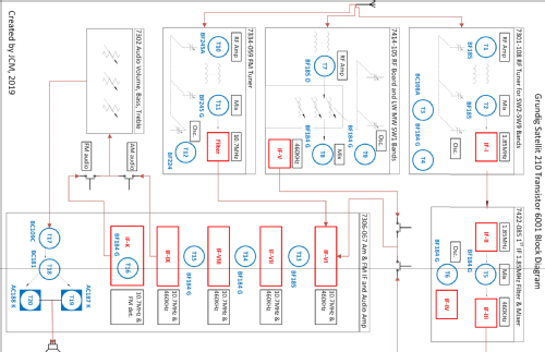
For all Satellit enthusiasts I have published a simplified block diagram that I hope will help on reading/interpret the original schematic diagram.
It has not been a simple job since the 210 is indeed quite complex, but at end I accomplished what I had in mind.
I have tried to keep the position in the functional diagram as close as possible similar with respect to the original schematic. This should also help you on cross-checking the two documents.
As all things produced in spare time, it is possible the document is not 100% accurate, in that case I will appreciate your feedback and comments to improve it.
You can find the document in the schematic section of the Grundig Satellit 210, file name is:
d_grundig_satellit210_block2_1.pdf
Alessandro.
for your convenience, I've included a direct dowload link. Enjoy.
Anexos
- click here to download (180 KB)
Alessandro Capitani, 09.Oct.08
What are other replacement light bulbs that can be used for this radio, that are OEM, and where can they be purchased?
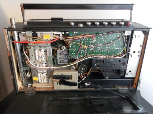
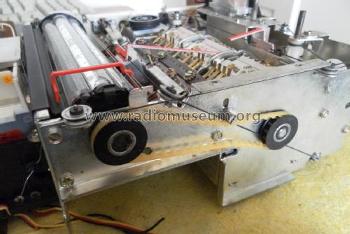
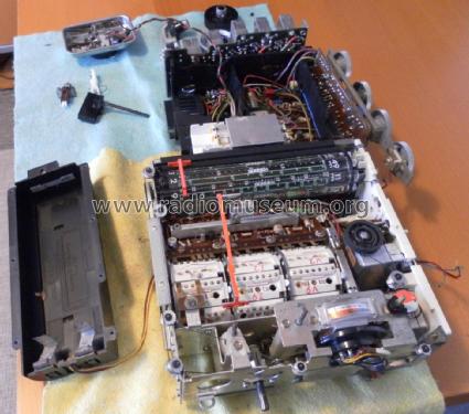
Other than using an eraser (for soft grafite) to clean the drum and using a cremolin based contact cleaner, what are other things that should be done for maintenance of this solid state master piece of 20'th century technology?
Omer
BTW The antenna for the Grundig Satellit 800 uses the same antenna as the 210 and can be purchased from Eton, USA.
Omer Suleimanagich, 09.Aug.05
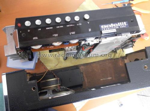
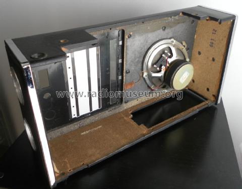
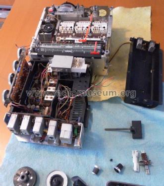
Zweites Problem: ich wage nicht das Chassis auszubauen, weil ich nicht weiß wie die seitlichen Bedienknöpfe für KW-Abstimmung und Trommeltuner und auch die Skalenseile darauf reagieren und wie der Ausbauvorgang ablaufen muß. Vielleicht hat jemand Erfahrung mit diesem Gerät, aber auch Serviceanleitung und Schaltschema würden weiterhelfen. Vielen Dank im Voraus.
Gerhard Heigl, 17.Aug.04